
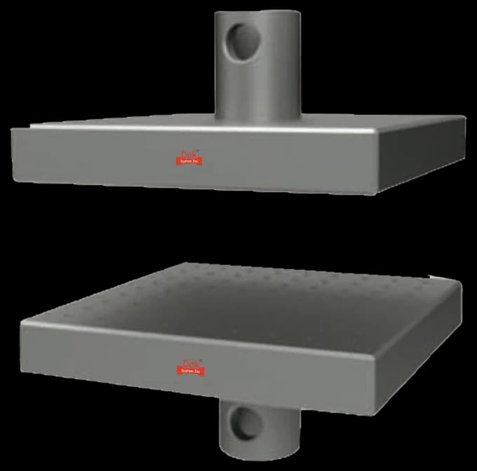
5 to 400 kNTJ-125
Direct Compression Fixture
A direct compression arrangement carries the plunger on the moving crosshead; the clamping ring holding the specimen is the part that has to be made or bought to the standard's dimensions.
Specifications
Testing standard
Standard Test Method for Measuring Static Puncture Strength of Geotextiles and Geosynthetic-Related Products Using a 50 mm Probe
Written and technically reviewed by Dak System Inc. engineeringLast reviewed
ASTM D6241 clamps a geotextile between rings and drives a 50 mm flat-ended probe through it at 50 mm/min, recording the force required. The probe is deliberately blunt and large: it loads the fabric in every direction at once, which is an index of puncture resistance rather than a simulation of a sharp stone.
From the test method to your testing system
Explore the DAK machines already listed for ASTM D6241, then review the grips, measurement and setup requirements below.
 Universal Testing MachineSeries 7200Explore the machine →
 Universal Testing MachineSeries 9000Explore the machine →
01Understand the method
A specimen is conditioned, seated flat between two clamping rings and held without pre-tension, with the clamp tightened progressively around its circumference rather than bolt by bolt. A 50 mm diameter flat-ended probe carried on the moving crosshead is then driven through the centre of the clamped opening at 50 mm/min (approximately 2 in./min), and the maximum force required to push it through is recorded. The rate is fixed outright rather than derived from a gauge length, because nothing here is being strained over a defined length: the clamped opening is 150 ± 2 mm across and the probe simply travels until the fabric ruptures. The specimen is marked at the ring line beforehand so that any fabric drawn in from under the clamp can be seen afterwards.
Resistance to blunt puncture, as an index. The 50 mm flat face loads a large area and stretches the fabric radially in every direction at once, which averages over the weave or the web instead of finding whatever weak point a needle would land on. That makes it repeatable enough for acceptance testing of commercial shipments, which the method states it is suitable for. It is not a prediction of installation survivability: angular aggregate, dragging and repeated loading are not reproduced by a single blunt push, and a specification asking about sharp stones is asking a different question.
02Prepare the specimen and test settings
Two pieces of geometry decide the result — the probe diameter and the clamped opening. Both are fixed by the method.
Puncture here means blunt puncture. A specification asking for resistance to angular aggregate is asking a different question, and this number will not answer it.
03Build the test setup on a DAK machine
Moderate force — puncture strengths commonly run from a few hundred newtons to several kilonewtons — delivered in compression, with the probe running true and central to the clamped opening. The clamping rings are the part that has to be made or obtained to the standard's dimensions, since the result scales with the size of the opening. Beyond that the requirement is straightforward: a held 50 mm/min and a load cell whose range suits the force rather than the frame. Speed is not the constraint — the specimen is normally through in well under a minute — but the rate must not drift, since the peak force is read from a curve produced at it.
A direct compression arrangement carries the plunger on the moving crosshead; the clamping ring holding the specimen is the part that has to be made or bought to the standard's dimensions.
SpecificationsDak verifies against whichever standard the method names, and where a class applies our frames sit a class tighter than it asks.
| The method asks for | Dak supplies | |
|---|---|---|
| Capacity | Moderate — puncture strengths commonly run from a few hundred newtons to several kilonewtons | Load cells from 1 kg to 60 ton on the Series 7200, and 0.5 to 100 kN on the Series 9000 |
| Force accuracy | ASTM D76 requirements for the testing machine | ISO 7500-1 Class 0.5, verified to ASTM E4, DIN 51221 and BS 1610 |
| Gripping | A 50 mm flat-ended probe on the crosshead, with the specimen clamped between rings | Our compression anvils, built to the specimen |
| Environment | 23 ± 2 °C standard laboratory atmosphere | 3009 series chambers, −150 °C to +400 °C — temperature only |
04Run the test
05Calculate, report and interpret
The maximum force recorded as the probe passes through the specimen
A force, not a stress. The probe area is fixed by the method, so dividing by it adds nothing and invites confusion with sharp-probe methods.
Compare only results from the same probe and clamp geometry
Puncture force scales with the clamped opening and the probe diameter, so figures from different methods are not interchangeable.
Uneven clamping, which biases where the puncture starts. Slippage at the ring, which inflates displacement, can depress the peak force, and is invisible in the data unless the specimen was marked. Reporting a force without the probe and clamp geometry, which makes it uncomparable with anything. And treating the figure as a survivability prediction, which is the interpretation the standard's own index-test description is written to prevent. Where installation damage genuinely is the question, the answer comes from a field trial with the actual aggregate and the actual plant, and the laboratory number is then used to rank candidates going into that trial rather than to replace it.
06Compare methods and find answers
| ASTM D6241 | ISO 12236 | |
|---|---|---|
| Probe | 50 mm flat-ended | 50 mm flat-ended with a chamfer |
| Known as | Static puncture | CBR puncture test |
| Nature | Index test | Index test |
| Interchangeable | No — cite the designation the specification names | No |
Same principle and the same probe diameter, but clamp geometry and specimen details differ enough that results should not be swapped between them. Geosynthetic specifications name one designation, and that is the one to run.
It is the ASTM static puncture test for geotextiles and geosynthetic-related products. The specimen is clamped between rings and a 50 mm diameter flat-ended probe is driven through its centre at 50 mm/min (approximately 2 in./min), with the maximum force recorded. The method describes itself as an index test and states that it is satisfactory for acceptance testing of commercial shipments.
Because a point measures the fabric's resistance at whatever it happens to land on — a yarn crossing, a gap in a weave, a thick or thin spot in a nonwoven — and the answer moves accordingly. A 50 mm flat face loads a large area and stretches the fabric radially in every direction at once, which averages over the structure and gives a repeatable figure. That multidirectional loading is also closer to what a rounded stone under a liner actually does.
No, and the standard says so by calling itself an index test. Installation damage involves angular aggregate, dragging, dropping and repeated loading, none of which a single blunt push reproduces. What the number does well is rank products against one another and confirm that a delivery matches what was specified, which is what acceptance testing needs.
Because tightening one bolt fully before moving to the next drags the fabric towards that side, so the specimen enters the test pre-tensioned unevenly. One sector then carries load before the others and the puncture starts there, below the fabric's real capability. Going progressively around the circumference, in stages, leaves the specimen flat and evenly held.
Mark it at the ring line before testing. If the mark has moved inwards afterwards, fabric was drawn in from under the clamp during the test, which inflates the recorded displacement and can lower the peak force. Without the mark, slippage is nearly invisible in the data and simply widens the scatter, where it looks like material variability.
No, it is a force. The probe area is fixed by the method, so dividing by it would add no information while inviting comparison with sharp-probe methods that use a quite different contact area. Reporting the force alongside the probe and clamp dimensions keeps clear what geometry produced it.
Not directly. Both use a 50 mm flat-ended plunger and both are index tests, but the clamp geometry and specimen details differ, and puncture force scales with the clamped opening. Geosynthetic specifications name one designation for exactly this reason, and running the other and converting is not an option the standards support.
Discuss your specimen, test requirements and reporting needs with DAK engineering.
This page describes the method as practised. The governing text is the current edition from the issuing body. Tell us what you are testing and we will answer with the machine, the fixture and a quotation.