Testing standard
ASTM F1306
Standard Test Method for Slow Rate Penetration Resistance of Flexible Barrier Films and Laminates
At a glance
- Test type
- Puncture & burst
- Published by
- ASTM
- Edition
- F1306-21(2025)
- Material
- Plastics, polymers & films
- Runs on
- Series 7200 and Series 9000
What the test does
A sheet of flexible film or laminate is clamped between two rings so that a circular area 35 mm across is left unsupported. A hemispherical probe, 3.2 mm in diameter as standard, is driven through the centre of that circle at 25 mm/min, normal to the film, until the film perforates. Force and probe travel are recorded from first contact to rupture, so the whole slow-push curve is captured rather than a single breaking figure. The film draws down around the probe before it gives way, and that drawing behaviour is what the method sets out to reproduce.
What it measures, and why it matters
Three quantities come out of the curve: maximum force, probe travel to that point, and the energy absorbed, found by integrating force over penetration. Peak force alone ranks films badly. A stiff, highly oriented laminate can carry a high load and then fail almost without warning, while a softer structure carries less but draws further and absorbs far more energy before it opens — and in a filled pack it is usually energy that separates a structure surviving a bone or a sharp product corner from one that does not. Because the probe advances slowly, the figures describe a deliberate push and must not be read across to impact.
Specimen
Pieces are cut large enough to be clamped around the full circumference with material to spare, so the test diameter is fully unsupported. Thickness is measured inside the area to be tested, since figures are commonly normalised per unit thickness and gauge varies across a web. A laminate does not behave the same punctured from each face, so the coated or sealant side must be presented consistently and recorded. Conditioning is for at least 40 h at 23 ± 2 °C and 50 ± 5 % relative humidity to Practice D618 Procedure A. Puncture data scatter, so take the replicate count from the edition in force rather than from habit.
What the machine must be capable of
No force capacity is prescribed. The governing requirement is that puncture occurs between 20 % and 80 % of the load range in use, which for thin barrier films normally means a compression load cell reading in the tens to low hundreds of newtons. The frame rating is rarely the limit; the load cell is, and choosing it is the most consequential decision here.
Crosshead speed is fixed at 25 mm/min. Polymer films are strongly rate-sensitive, and the method deals with that by removing the variable rather than exploring it, so a test at another speed yields numbers nobody can compare with. Acquisition must give at least one point per 0.1 mm of penetration; anything coarser rounds off the peak and corrupts the energy integral. No extensometer is involved — penetration comes from crosshead travel, which is acceptable because the forces are low and load-train deflection with them, though a compliant adaptor still shows up as extra apparent travel.
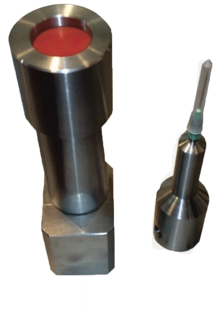
The fixture is a ring clamp, pneumatic or mechanical, presenting the 35 mm test diameter with the probe driven through its centre. Other probe diameters are allowed provided the ratio of clamped diameter to probe diameter stays at least 10:1. That ratio keeps the deformation a membrane-stretching problem across the whole disc; drop below it and the probe shears the film locally instead — a different failure and a different number. Testing is in the conditioning atmosphere, not merely at room ambient.
What goes wrong in practice
Slip at the clamp is the commonest fault and the hardest to see. Film drawn in from outside the ring adds travel that never came from the test area, inflating penetration and energy while leaving a curve that looks plausible. Polished clamp faces, or clamp pressure set for a thicker structure, are the usual causes.
A probe that is not centred loads one side of the membrane first and punctures early; once alignment has drifted, the error is systematic rather than random. Probe wear is the same fault in slow motion — a hemisphere that has scratched or flattened stops stretching the film and starts cutting it, so results drift downwards over months without any single test looking wrong.
Load-range mismatch is endemic in shared laboratories: a cell sized for tensile work on the same frame puts a small puncture event down in its own noise and returns energy values that are largely integration error.
Related and equivalent standards
ASTM D5748, protrusion puncture of stretch wrap film, is the method most often confused with this one. It addresses a different specimen population under a different probe arrangement, so values from the two are not interchangeable in a specification.
The wider confusion is with instrumented high-speed puncture methods: because polymers stiffen and embrittle with rate, those rank materials differently, and a structure that does well here may still not survive a dropped pack. No direct cross-body equivalent to F1306 was confirmed.
Running ASTM F1306 on the Series 7200 and Series 9000
Dak verifies against whichever standard the method names, and where a class applies our frames sit a class tighter than it asks.
| The method asks for | Dak supplies | |
|---|---|---|
| Capacity | No force capacity is prescribed. The method asks only that puncture occur between 20 % and 80 % of the load range in use, which for thin barrier films and laminates normally means a compression load cell in the tens to low hundreds of newtons rather than a large frame; the frame rating is almost never the limit, the load cell is. | Load cells from 1 kg to 60 ton on the Series 7200, and 0.5 to 100 kN on the Series 9000 |
| Gripping | Pneumatic or mechanical ring clamp with a driven hemispherical penetration probe | Our compression anvils, built to the specimen |
| Environment | 23 ± 2 °C and 50 ± 5 % RH; condition at least 40 h to Practice D618 Procedure A and test in the same atmosphere | 3009 series chambers, −150 °C to +400 °C — temperature only |
This page describes the method as practised. The governing text is the current edition from the issuing body. Tell us what you are testing and we will answer with the machine, the fixture and a quotation.