Testing standard

ASTM D6415

Standard Test Method for Measuring the Curved Beam Strength of a Fiber-Reinforced Polymer-Matrix Composite

Written and technically reviewed by Dak System Inc. engineeringLast reviewed

ASTM D6415 loads a 90° curved composite beam in four-point bending so the bend opens, generating tension through the thickness until the radius delaminates. It produces the out-of-plane structural failure data a curved composite detail is designed against. The current edition is D6415/D6415M-22.

At a glance

Test type
Fracture toughness
Published by
ASTM
Edition
D6415/D6415M-22

What the test does

A 90° curved beam specimen — two straight legs joined by a 90° bend with a 6.4 mm inner radius — is loaded in four-point bending so that the bend is opened, increasing its radius of curvature. Opening a curved laminate that way generates tensile stress through the thickness, at right angles to the plies, and the specimen delaminates in the radius. The load at which it does gives the curved beam strength.

What it measures, and why it matters

Composite laminates are strong in the plane of their fibres and weak through the thickness, where only the matrix carries load. Any curved feature in a composite structure — the radius of an L-shaped frame, a C-section spar, a stiffener flange — turns an applied moment into an interlaminar tensile stress in the radius. That stress has nothing holding it but resin.

It is the classic failure of a composite part that looks fine everywhere else. The straight sections are far from their limits and the radius delaminates first, often with no external sign until the part is loaded again.

The method exists to produce structural design data for that case, and the standard says as much: it is intended to produce out-of-plane structural failure data for structural design and analysis, quality assurance, and research and development. Knowledge of a laminate's resistance to interlaminar fracture is useful for product development and material selection.

Curved beam strength is a strength, expressed as a moment per unit width, rather than a fracture toughness. Where the interlaminar tensile stress itself is wanted, it is derived from the curved beam strength using the specimen geometry.

A moulded specimen, not a machined one

Almost every other composite coupon is cut from a flat panel. This one is laid up over a radius, which makes how it was made part of what is being measured.

Geometry
A 90° curved beam: two straight legs joined by a 90° bend
Inner radius
6.4 mm
Material
Continuous fibre-reinforced polymer matrix composite
Radius quality
Ply bridging, resin-rich pockets, corner thinning and voids all reduce the resultPracticeThese are real manufacturing effects, which is exactly why the test is useful. They are not specimen defects to be eliminated.
Conditioning
To the moisture state the test plan requires, and reportedInterlaminar tension is matrix-dominated.
Make the specimen the way the part is made
DakA coupon laid up more carefully than the article it represents gives a number that is high, defensible and not about the part.

Loading and rate

Loading
Four-point bending that opens the bend, increasing its radius of curvature
Rate
As specified in the method; the figure sits in the purchased text
Reported
Curved beam strength, as a moment per unit width
Measure the loading bar diameter and spacing
DakBoth enter the calculation directly, so they are measured rather than assumed from the drawing.

From failure load to interlaminar tension

Curved beam strengthCBS

The applied moment per unit width at failure

applied moment
derived from the failure load and the loading bar geometry
width
the specimen width, mm

A strength, not a fracture toughness. It is reported as a moment per unit width rather than a stress.

Interlaminar tensile stress

Derived from the curved beam strength using the specimen radius and thickness

inner radius
6.4 mm on the standard specimen
thickness
the laminate thickness through the bend

This is why the report has to carry radius and thickness: without them the stress cannot be recovered from the strength afterwards.

Why a radius fails first

An applied moment on a curved laminate becomes through-thickness tension

Only the matrix resists it. The straight sections can be far from their limits while the corner delaminates.

How the test runs

  1. 01Lay up and cure curved beam specimens on a radiused tool, as the part is made.
  2. 02Measure leg thickness, bend thickness and width.
  3. 03Record the inner radius as manufactured.
  4. 04Condition to the required moisture state.
  5. 05Set the four loading bars to the specified diameters and spacings, and measure them.
  6. 06Check every bar rolls freely.
  7. 07Load in four-point bending so the bend opens.
  8. 08Record the failure load.
  9. 09Inspect the failure: reject any specimen failing in a leg or at a loading bar.
  10. 10Compute curved beam strength, and interlaminar tensile stress where required.

A loading bar that does not roll adds a friction couple that is not in the analysis. The calculated strength drifts high, consistently, and nothing in the trace shows it.

Grips and fixtures for this method

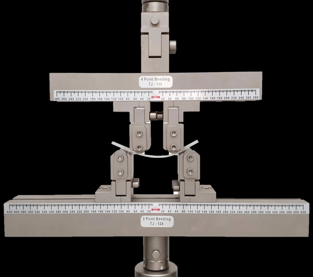
Four point bending fixture with two inner and two outer supports
Uniform momentTJ-165

Four Point Bend Fixture

Four cylindrical loading bars, two on each leg, applying the opening moment. Bar diameter and spacing are specified and enter the calculation, so they are measured; every bar has to roll freely as the legs rotate, or friction adds a couple the analysis does not include.

Specifications
Self-identifying

Load Cells

Curved beam specimens fail in the low kilonewtons. A cell sized for the specimen resolves the initiation load, which is the whole result.

Specifications

What the report has to contain

  • Reference to ASTM D6415/D6415M and the edition
  • Fibre, matrix, lay-up and cure schedule
  • How the specimen was manufactured, and on what tool
  • Inner radius as manufactured
  • Leg thickness, bend thickness and specimen width
  • Loading bar diameter and spacing as measured
  • Moisture conditioning state
  • Loading rate
  • Failure load and curved beam strength for each specimen
  • Failure location, and any specimen rejected for failing outside the radius

What the machine must be capable of

Forces are moderate — commonly in the low kilonewtons — so a 5 to 50 kN frame with a load cell sized for the specimen and force accuracy to ASTM E4 is appropriate.

The fixture is what needs care. Four cylindrical loading bars, two on each leg, apply the opening moment, and they have to be free to roll as the legs rotate. A bar that binds adds a friction couple that is not in the analysis and the calculated strength drifts high. Loading bar diameter and spacing are specified and are used directly in the calculation, so they are measured rather than assumed.

Displacement is recorded, but the result comes from the failure load and the geometry; no strain measurement on the specimen is required for the basic result.

What goes wrong in practice

Specimens laid up to a standard the production part will never see are the most misleading failure, because the number is high and defensible and does not describe the article. Loading bars that do not roll add friction. Failure outside the radius — in a leg, or at a loading bar — is an invalid test rather than a low result. And reporting a curved beam strength without the specimen thickness and radius makes it impossible to derive the interlaminar tensile stress afterwards.

Strength or toughness — which through-thickness test

Four ways of interrogating the weak direction of a laminate. They are not alternatives.

Curved beam (D6415)Mode I (D5528)Mode II (D7905)Flatwise tension (C297)
ResultA strength, moment per unit widthG_Ic, J/m²G_IIc, J/m²A stress, MPa
Pre-crackNone — failure initiatesYesYesNone
AnswersWill this radius survive the momentHow fast will a crack growHow fast under shearIs the bond sound
SpecimenA moulded 90° beamA flat DCBA flat ENF beamA bonded block
Sensitive toHow the radius was madeResin toughnessResin toughnessBond quality

Curved beam strength measures initiation in a real manufactured feature; the fracture methods measure propagation in an idealised one. A design that needs both is common, and one does not substitute for the other.

Questions we are asked about this test

What is ASTM D6415?

ASTM D6415, published as D6415/D6415M, measures the curved beam strength of a fibre-reinforced polymer matrix composite. A 90° curved beam with a 6.4 mm inner radius is loaded in four-point bending so that the bend opens, which generates tensile stress through the thickness until the radius delaminates. The current edition is D6415/D6415M-22.

Why do curved composite features fail before straight ones?

Because a moment applied to a curved laminate turns into tension through the thickness, and through the thickness only the matrix carries load. The straight sections of an L-shaped frame or a C-section spar can be well within their limits while the radius joining them delaminates. It is the classic failure of a composite part that looks fine everywhere else, and it usually gives no external warning.

Is this a fracture toughness test?

No. It produces a strength — a moment per unit width at failure — rather than a strain energy release rate. There is no pre-crack: the specimen fails by initiation in an as-manufactured radius. The fracture methods, ASTM D5528, D7905 and D6671, measure how fast an existing delamination grows. A design usually needs both answers and neither substitutes for the other.

Why does it matter how the specimen was made?

Because the specimen is a moulded article rather than a coupon cut from flat stock. Ply bridging over the radius, resin-rich pockets on the inside of the corner, thinning through the bend and voids from poor debulking all reduce the strength — and all of them are real effects that occur in production parts. A specimen laid up with more care than the article it represents produces a number that is high, defensible and about nothing in the aircraft.

What is the most common invalid result?

Failure outside the radius. A specimen that breaks in a leg, or crushes at a loading bar, has not measured curved beam strength and is discarded rather than recorded as a low value. The other common fault is a loading bar that does not roll: friction between bar and leg adds a couple the analysis does not account for, and the calculated strength drifts consistently high with nothing in the force trace to show it.

What machine does it need?

A modest frame with a good four-point fixture. Failure loads are commonly in the low kilonewtons, so a 5 to 50 kN frame with a load cell sized for the specimen and force accuracy to ASTM E4 is appropriate. The fixture is where the attention goes: four bars of specified diameter and spacing, all free to roll, with the geometry measured rather than assumed because it enters the calculation directly.

How is interlaminar tensile stress obtained from it?

By deriving it from the curved beam strength using the specimen geometry — principally the inner radius and the laminate thickness through the bend. That is why the report must carry both: a curved beam strength quoted without the radius and thickness it came from cannot be converted afterwards, and a value taken from one geometry does not transfer to a part with a different corner.


Running ASTM D6415 on the Series 7200 and Series 9000

Dak verifies against whichever standard the method names, and where a class applies our frames sit a class tighter than it asks.

The method asks forDak supplies
CapacityModerate — commonly in the low kNLoad cells from 1 kg to 60 ton on the Series 7200, and 0.5 to 100 kN on the Series 9000
Force accuracyASTM E4Verified to ASTM E4, and to ISO 7500-1 Class 0.5
GrippingFour cylindrical loading bars, two on each leg, all free to rollOur bend fixtures, built to the specimen
EnvironmentMoisture conditioning to the state the test plan requires; interlaminar tension is matrix-dominated3009 series chambers, −150 °C to +400 °C — temperature only

This page describes the method as practised. The governing text is the current edition from the issuing body. Tell us what you are testing and we will answer with the machine, the fixture and a quotation.