Standard Test Method for Determination of the Mode II Interlaminar Fracture Toughness of Unidirectional Fiber-Reinforced Polymer Matrix Composites
Written and technically reviewed by Dak System Inc. engineering·Last reviewed
ASTM D7905 measures mode II interlaminar fracture toughness, G_IIc, using the end-notched flexure geometry: a unidirectional beam with a mid-plane starter delamination is loaded in three-point bending so the crack faces slide rather than open. It is limited to unidirectional carbon-fibre and glass-fibre laminates. The current edition is D7905/D7905M-19e1.
A unidirectional laminate beam with a thin non-adhesive insert at the mid-plane, forming a starter delamination at one end, is loaded in three-point bending with the delaminated end overhanging one support. This is the end-notched flexure, or ENF, geometry. Bending puts the two halves of the beam into relative sliding at the mid-plane, so the delamination is driven forward in shear rather than by being pulled open.
The force and the crosshead displacement are recorded, the delamination length is known from the specimen preparation and from a compliance calibration, and from those the critical strain energy release rate in mode II — G_IIc — is calculated.
What it measures, and why it matters
Delamination is the characteristic failure of a laminated composite, and it happens in three modes: opening, sliding and tearing. Mode I, the opening mode, is measured by ASTM D5528; this method covers mode II, the in-plane sliding mode.
Mode II toughness is usually several times mode I toughness in the same material, and the ratio between them is one of the more revealing numbers a composites laboratory produces. It says how much of the resistance comes from the resin itself and how much from fibre bridging and other mechanisms that only operate when the crack faces separate.
The application is damage tolerance. Design allowables for a composite structure that must survive impact damage and continue to carry load are built on delamination resistance, and mode II governs the growth of a delamination under in-plane shear — the loading a stiffened panel sees. Aerospace, wind energy, automotive and marine structures all use these values.
The scope is limited to unidirectional carbon-fibre and glass-fibre reinforced laminates. The method notes it may prove useful for other types and classes of composite, with interferences noted.
Specimen, and the insert that starts the crack
Insert thickness is the variable that most often invalidates a mode II result, and it is decided in the layup room rather than in the laboratory.
Material
Unidirectional carbon-fibre and glass-fibre reinforced laminatesThe method may prove useful for other types and classes of composite, with interferences noted.
Specimen
A straight-sided unidirectional beam with a mid-plane insert at one end
Insert
A thin non-adhesive film forming the starter delaminationThick film blunts the crack tip and the first measured toughness comes out high.
Fibre alignment
Straight and on-axis through the beamPracticeFibres even slightly off-axis let the delamination wander out of the mid-plane, and the geometry the analysis assumes no longer holds.
Conditioning
To the moisture state the test plan requires, and reportedMode II toughness is matrix-dominated and moisture plasticises the matrix.
Reject a specimen whose delamination has migrated
DakA crack that has left the mid-plane invalidates the specimen entirely, and it is not always obvious once the beam is unloaded.
Loading and the compliance calibration
Geometry
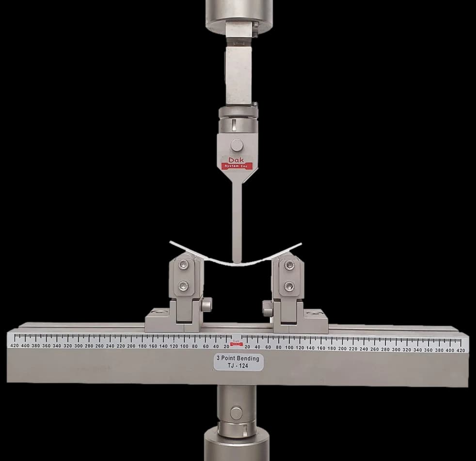
Three-point bending, with the delaminated end overhanging one support
Rate
As specified in the method; the figure sits in the purchased text
Recorded
Force and displacement, continuouslyThe fracture event is fast and the peak defines the result.
Compliance calibration
Runs at known crack lengths, before the fracture runThis is what turns force and displacement into a crack length. Anything that changes the fixture between calibration and test corrupts it.
Keep the fixture identical between calibration and fracture
DakA roller that binds, or a fixture that beds in, changes the compliance and therefore the toughness — silently.
Mode II, and how it differs from mode I
Critical strain energy release rate, mode IIG_IIc
Derived from the peak force, the beam compliance and the crack length
peak force
the load at which the delamination advances, N
compliance
displacement per unit force, from the calibration runs
crack length
the delamination length, from preparation and calibration
Reported in joules per square metre. The calculation is written into the method and depends on the calibration being valid.
The three fracture modes—
Opening, in-plane sliding, tearing
mode I
opening — ASTM D5528
mode II
in-plane sliding — this method
mixed mode
a combination — ASTM D6671
The G_IIc to G_Ic ratio—
Mode II toughness is usually several times mode I toughness
The ratio says how much resistance comes from the resin itself and how much from fibre bridging and other mechanisms that only operate when the crack faces separate.
How the test runs
01Lay up a unidirectional panel with a thin non-adhesive insert at the mid-plane.
02Cut straight-sided beams and measure width and thickness.
03Mark the crack lengths required for the compliance calibration.
04Condition to the required moisture state.
05Set the three-point bend fixture with the specified span and roller radii.
06Run the compliance calibration at the marked crack lengths.
07Position the specimen for the fracture run with the delaminated end overhanging.
08Load continuously at the specified rate until the delamination advances.
09Record the peak force and the displacement.
10Compute G_IIc from the calibration, the peak force and the crack length.
11Inspect the fracture surface and reject any specimen whose crack left the mid-plane.
Grips and fixtures for this method
Adjustable spanTJ-124
Three Point Bend Fixture
The ENF geometry is three-point bending with the delaminated end overhanging one support. Roller radius and span are specified and enter the calculation, and the rollers must turn freely — a binding roller changes the fixture compliance between the calibration runs and the fracture run.
An ENF specimen fails in the hundreds of newtons to low kilonewtons. A cell sized for the specimen is what resolves a peak that arrives quickly, and the peak is the result.
Fracture surface observations, and any specimen rejected for crack migration
What the machine must be capable of
Forces are modest — an ENF specimen fails in the hundreds of newtons to low kilonewtons — so a 5 to 10 kN frame with a load cell sized for the specimen is right, with force accuracy to ASTM E4.
What the test really needs is a stiff, well-aligned three-point bend fixture with rollers of the specified radius that turn freely. The compliance calibration procedure depends on the fixture behaving consistently between the calibration runs and the fracture run, so a fixture that beds in or a roller that binds corrupts the calibration and therefore the toughness.
Displacement has to be measured accurately and, ideally, on the specimen rather than from crosshead travel, because machine compliance enters the compliance calibration directly. Data must be logged continuously: the fracture event is fast and the peak defines the result.
What goes wrong in practice
An insert film that is too thick blunts the starter and inflates the first toughness value. Delamination that migrates out of the mid-plane invalidates the specimen entirely and is not always obvious afterwards. A worn or binding roller changes the fixture compliance between calibration and test. And crack length taken from an assumption rather than from the compliance calibration produces a G_IIc that is precise and inaccurate.
The delamination methods
Three modes, three documents, and one screening test that is often mistaken for a fourth.
Mode I (D5528)
Mode II (D7905)
Mixed mode (D6671)
Short beam (D2344)
Crack faces
Pulled open
Slide over each other
Both
No pre-crack
Specimen
Double cantilever beam
End-notched flexure beam
Mixed-mode bending
A short flexure coupon
Result
G_Ic, J/m²
G_IIc, J/m²
G_c at a mode ratio
Apparent shear strength, MPa
Is it a fracture test
Yes
Yes
Yes
No — a quality screen
Typical magnitude
Lowest
Several times G_Ic
Between the two
Not comparable
ASTM D2344 short-beam strength is a quality-control screen and not an interlaminar fracture measurement, however often the two are quoted side by side. It gives an apparent strength on an uncracked coupon and carries no strain energy release rate.
Questions we are asked about this test
What is ASTM D7905?+
ASTM D7905, published as D7905/D7905M, determines the mode II interlaminar fracture toughness of unidirectional fibre-reinforced polymer matrix composites using the end-notched flexure test. A beam with a starter delamination at its mid-plane is loaded in three-point bending, driving the crack forward in shear, and G_IIc is computed from the peak force and a compliance calibration. The current edition is D7905/D7905M-19e1.
What is mode II, and how does it differ from mode I?+
The two describe how a crack is loaded. Mode I is the opening mode, where the crack faces are pulled directly apart — measured by ASTM D5528 with a double cantilever beam. Mode II is the in-plane sliding mode, where the faces slide over one another. Mode II toughness is typically several times the mode I value in the same material, because sliding mobilises friction and matrix shear that opening does not.
Why does the insert thickness matter?+
Because it sets the sharpness of the starter crack. The insert is a thin non-adhesive film laid at the mid-plane during layup, and if it is too thick the resulting crack tip is blunt rather than sharp. A blunt tip needs more energy to start moving, so the first measured toughness comes out high — and it is the first value that is usually quoted. The limit is specified for that reason and it is a layup-room control, not a laboratory one.
What is the compliance calibration for?+
It relates the beam compliance, which is displacement per unit force, to the crack length. Running the specimen at several known crack lengths before the fracture run builds that relationship, so the crack length during the fracture event can be inferred rather than watched. It also means the fixture has to behave identically between the calibration and the test: a roller that binds or a fixture that beds in changes the compliance and moves the answer without anything appearing wrong.
Why is it limited to unidirectional laminates?+
Because the analysis assumes the delamination stays in the mid-plane of a beam whose two halves are identical and isotropic in the plane of loading. Cross-plied or woven laminates deflect the crack out of that plane and introduce mode mixing, so the geometry no longer isolates mode II. The standard notes the method may prove useful for other types and classes of composite, with interferences noted — which is an invitation to proceed with care, not a general permission.
What is it used for commercially?+
Damage tolerance. Design allowables for composite structures that must survive impact damage and keep carrying load are built on delamination resistance, and mode II governs how a delamination grows under in-plane shear — the loading a stiffened aerospace panel, a wind turbine blade shell or an automotive floor sees. Material selection between competing resin systems is also settled on these numbers more often than on tensile strength.
What machine does it need?+
A small frame with a stiff, well-aligned three-point bend fixture. Forces are in the hundreds of newtons to low kilonewtons, so a 5 to 10 kN frame with a load cell sized for the specimen and force accuracy to ASTM E4 is right. What matters more than the frame is fixture consistency and accurate displacement measurement, because machine compliance enters the compliance calibration directly and therefore enters G_IIc.

This page describes the method as practised. The governing text is the current edition from the issuing body. Tell us what you are testing and we will answer with the machine, the fixture and a quotation.