
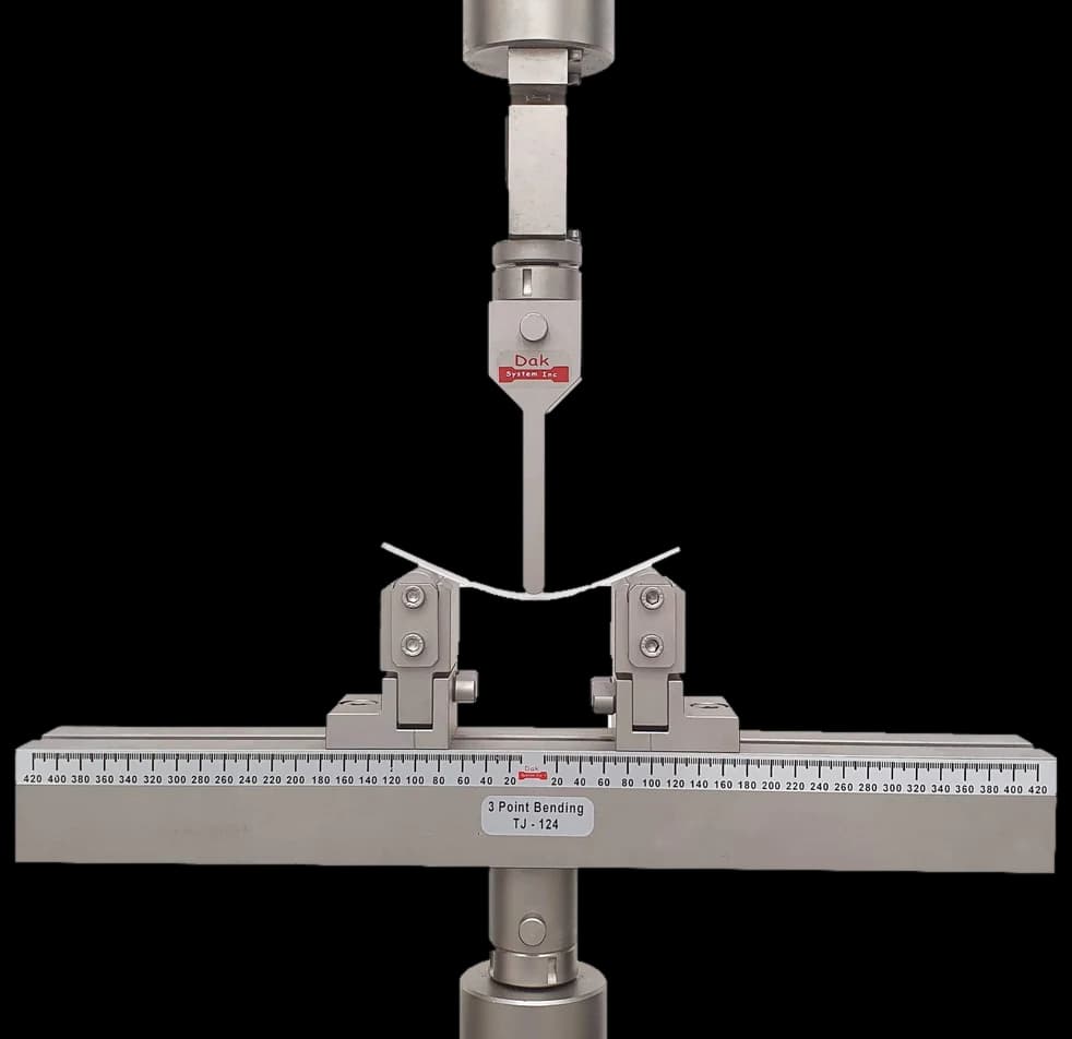
Adjustable spanTJ-124
Three Point Bend Fixture
A three-point bend fixture with adjustable span and the roller diameters the method specifies — span-to-depth ratio is set on the fixture, not assumed.
Specifications
Testing standard
Standard Test Methods for Plane-Strain Fracture Toughness and Strain Energy Release Rate of Plastic Materials
Written and technically reviewed by Dak System Inc. engineeringLast reviewed
ASTM D5045 determines the plane-strain fracture toughness KIc and the critical strain energy release rate GIc of plastics, using either a single-edge-notch bend or a compact tension specimen. The result is valid only if size and sharpness criteria are satisfied, and those are checked after the test rather than before.
From the test method to your testing system
Explore the DAK machines already listed for ASTM D5045, then review the grips, measurement and setup requirements below.
 Universal Testing MachineSeries 7200Explore the machine →
 Universal Testing MachineSeries 9000Explore the machine →
01Understand the method
A specimen is machined to either the single-edge-notch bend or the compact tension geometry, notched, and given a sharp crack at the notch root. After conditioning it is loaded at a constant rate to fracture — in three-point bending for SENB, or through clevises and pins for CT — while force and displacement are recorded. The specimen is then opened and the crack length measured on the fracture surface. KIc is calculated using the geometry function for the specimen type, and GIc is derived from it using the elastic modulus and Poisson's ratio.
The resistance of a plastic to a crack that already exists — a different and often more relevant question than how strong it is. A tensile strength describes an unblemished specimen; real parts contain weld lines, gate marks, scratches and moulded-in stress concentrations, and what governs whether they survive is how readily a crack runs from them. The distinguishing feature of this method is that it does not simply return a number: it returns a number plus a question about whether that number is a material property at all, and the answer is only available after the test.
02Prepare the specimen and test settings
A number always comes out. Whether it is a material property depends on criteria you check afterwards.
This is a linear elastic method. If the material yields substantially before the crack runs, the assumptions fail and the result is not a valid KIc, however cleanly the specimen broke.
03Build the test setup on a DAK machine
Moderate force, a slow and steady rate, and the right fixture for the geometry — a three-point bend rig at the specified span for SENB, or clevises and pins that let a compact tension specimen rotate freely as the crack opens. The method's basic test condition is 23 °C with a crosshead rate of 1.67 × 10⁻⁴ m/s — 10 mm/min (0.4 in./min) — and both the loading rate and the loading time go on the report form, because a plastic is viscoelastic and its toughness belongs to the time scale it was measured on. Speeds above 1 m/s, or loading times under 1 ms, are to be avoided: dynamic effects start to corrupt the trace. Where crack opening displacement is required, a clip gauge across the notch is needed. Data capture matters more than capacity here, because the trace has to be examined for linearity: substantial non-linearity means the material yielded before the crack ran, and no valid KIc can be extracted from it.
A three-point bend fixture with adjustable span and the roller diameters the method specifies — span-to-depth ratio is set on the fixture, not assumed.
Specifications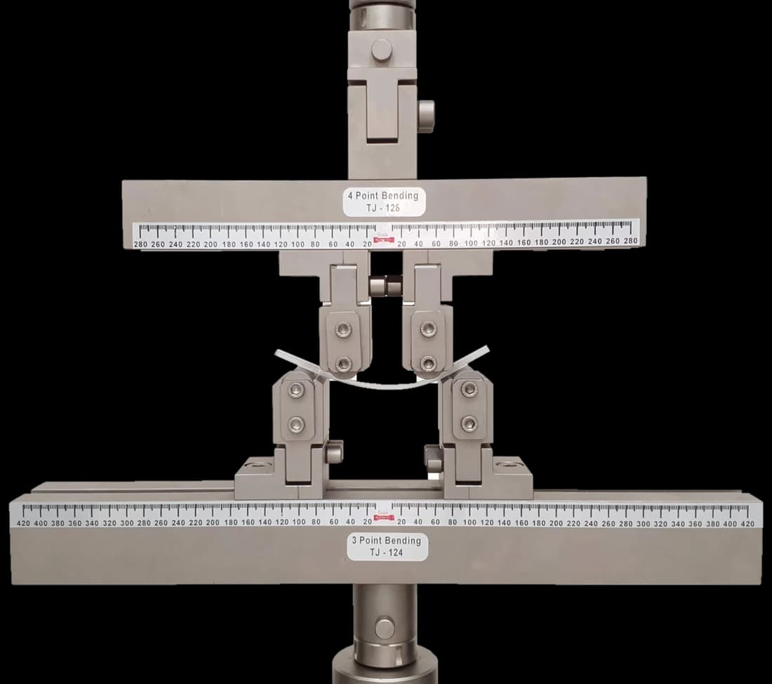
Four-point loading where the specification calls for it, putting a length of the specimen under constant moment rather than concentrating it under one nose.
SpecificationsDak verifies against whichever standard the method names, and where a class applies our frames sit a class tighter than it asks.
| The method asks for | Dak supplies | |
|---|---|---|
| Capacity | Low to moderate — plastics fracture specimens commonly fail between tens of newtons and a few kilonewtons | Load cells from 1 kg to 60 ton on the Series 7200, and 0.5 to 100 kN on the Series 9000 |
| Force accuracy | unknown — ASTM E4 is not among this method's referenced documents, which name no force-verification standard and no accuracy class | ISO 7500-1 Class 0.5 — the method sets no class of its own |
| Gripping | A three-point bend fixture for SENB, or clevises and pins for the compact tension geometry | Our bend fixtures, built to the specimen |
| Environment | 23 ± 2 °C standard laboratory atmosphere | 3009 series chambers, −150 °C to +400 °C — temperature only |
04Run the test
05Calculate, report and interpret
KIc = (F / (B × W^½)) × f(a/W)
The geometry function differs between the two specimen types, so the correct one must be used for the geometry actually tested.
GIc = KIc² × (1 − ν²) / E
Derived from KIc, so it inherits every error in it and adds the uncertainty in E and ν. Both must be for the same material and condition.
Specimen dimensions checked against the measured toughness and the yield stress
Circular by design: the size needed depends on the answer, so validity can only be confirmed afterwards.
Quoting an invalid result as a material property. The size criterion is computed from the measured toughness and the yield stress, so it can only be applied retrospectively — which means every specimen needs checking rather than the set being assumed valid because the first one was. Testing from a machined notch without introducing a sharp crack, which reads high. Ignoring a non-linear trace. And reporting GIc without the modulus and Poisson's ratio used to derive it, which makes the second figure unverifiable. Measuring the crack from outside the specimen belongs on the list too: a sharp pre-crack is very fine and its front is rarely straight, so it can only be measured honestly once the specimen is open.
06Compare methods and find answers
| ASTM D5045 | ISO 13586 | |
|---|---|---|
| Outputs | KIc and GIc | KIc and GIc |
| Geometries | SENB and CT | SENB and CT |
| Basis | Linear elastic fracture mechanics | Linear elastic fracture mechanics |
| Cite | Whichever the specification names | Whichever the specification names |
Closely aligned methods for the same quantities. Differences lie in the detail of specimen preparation and validity checking, so results should not be pooled across the two without confirming those match.
It is the ASTM method for the plane-strain fracture toughness KIc and the critical strain energy release rate GIc of plastics. Two geometries are covered — single-edge-notch bending and compact tension — and a pre-cracked specimen is loaded to fracture in the linear elastic range. The current designation is ASTM D5045-14(2022).
To keep the crack tip in plane strain. A thin specimen deforms through its thickness and sits in plane stress, where the apparent toughness is higher and depends on the thickness — so it is not a material property at all. Enough thickness constrains that deformation and produces a value that belongs to the material rather than to the specimen. This is why a KIc measured on too thin a specimen reads high and cannot be used in design.
Because the size criterion depends on the toughness, and the toughness is what you are measuring. The required dimensions are computed from the measured toughness and the material's yield stress, so the check is necessarily retrospective. In practice you estimate, machine generously, test, and then confirm — and a specimen that turns out to have been too small yields a number that must not be quoted as a KIc.
Because a blunt notch distributes stress over a larger radius and needs more load to propagate, so the measured toughness reads high. The method requires a crack sharp enough to give a minimum value of toughness — in practice a natural crack initiated at the machined notch root, often by a razor. A machined notch alone is one of the commonest ways an invalid, flattering result is produced.
Then the linear elastic assumptions behind KIc may not hold. This is a linear elastic fracture mechanics method: it assumes the plastic zone at the crack tip is small compared with the specimen. Substantial non-linearity means the material yielded appreciably before the crack ran, and the calculated KIc is not valid — a different framework, such as a J-integral method, is needed for that behaviour.
GIc is calculated from KIc using the elastic modulus and Poisson's ratio. That means it inherits every error in the KIc and adds the uncertainty in the two elastic constants, which must be for the same material in the same condition. It is not an independent measurement, and reporting both without saying which values of E and ν were used leaves the second unverifiable.
Because you cannot see it accurately until the specimen is open. A sharp pre-crack is very fine and its front is rarely straight, so measuring it from the outside underestimates it and does so inconsistently. Opening the specimen and measuring the crack length on the fracture surface, across the front, is the only reliable way — which is why crack length is a post-test measurement in this method.
Discuss your specimen, test requirements and reporting needs with DAK engineering.
This page describes the method as practised. The governing text is the current edition from the issuing body. Tell us what you are testing and we will answer with the machine, the fixture and a quotation.