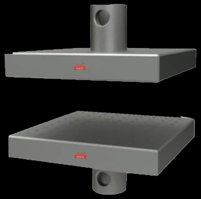
Direct Compression Fixture
A direct compression arrangement carries the test blocks; the blocks themselves are made to the geometry the device requires and are part of the test set-up rather than a standard accessory.
SpecificationsTesting standard
Standard Test Methods for Intervertebral Body Fusion Devices
Written and technically reviewed by Dak System Inc. engineeringLast reviewed
ASTM F2077 is a set of test methods for intervertebral body fusion device assemblies — static and dynamic compression, compression-shear and torsion. Its stated purpose is to provide a basis for mechanical comparison between devices, including devices intended for different spinal levels, rather than to predict clinical performance.
An intervertebral body fusion device is seated between test blocks made to reproduce how it sits in the intradiscal space, and loaded in one of three modes — axial compression, compression-shear, or torsion — either statically to a defined endpoint or dynamically to a defined run-out. The static tests yield a yield load, an ultimate load and a stiffness, determined from the load-displacement curve by the method's own construction rules. The dynamic tests yield the maximum load at which the device survives to the run-out cycle count. All are reported for a stated spinal level: lumbar, thoracic or cervical.
A basis for comparison, which is what the standard says of itself. Its purpose is to let past, present and future non-biologic device assemblies be measured on common terms, including devices intended for different spinal levels and applied by different methods. That is a real and useful thing, and it is not a prediction of clinical behaviour — a submission that reads it as one is claiming more than the method supports. Compression-shear matters particularly, because pure axial compression is a friendlier load case than the spine actually applies, and many devices fail under the combination at loads they survive alone.
The standard exists so that a new device can be measured against past and present ones on the same terms.
The standard says it provides a basis for mechanical comparison among past, present and future device assemblies. It does not claim to predict how a device will behave in a patient, and a submission that reads it that way is overreaching.
Yield load, ultimate load and stiffness from the load-displacement curve
Defined on the curve by the method's own construction rules, not by inspection.
The maximum load at which the device survives to run-out
Reported with the run-out cycle count and the loading mode. A fatigue figure without both is not interpretable.
Same loading mode, same spinal level, same test block geometry
Comparing across any of those three is comparing set-ups rather than devices.

A direct compression arrangement carries the test blocks; the blocks themselves are made to the geometry the device requires and are part of the test set-up rather than a standard accessory.
SpecificationsA load cell matched to the device's rating rather than to the frame — cervical devices are tested at a small fraction of lumbar loads.
SpecificationsStatic and dynamic loading in three modes, with capacity chosen for the spinal level rather than for the frame — cervical devices are tested at a small fraction of lumbar loads, and a load cell sized for the larger will not resolve the smaller with any traceable accuracy. Dynamic testing needs force verified at the test frequency and waveform, not only under static calibration: a frame that under-delivers at speed passes that error into every one of several million cycles, and nothing in the record reveals it afterwards.
Quoting a fatigue load without the run-out cycle count, which makes the claim uninterpretable — surviving a million cycles and surviving ten million at the same load are different statements. Comparing devices tested on different block geometries. Verifying force only statically. Recording the cycle at which a device failed without photographing or sectioning it, when where it cracked tells the designer far more than when. And presenting the results as evidence of clinical performance rather than of mechanical comparison.
| ASTM F2077 | ASTM F2267 | |
|---|---|---|
| Measures | Strength and fatigue of the device | Subsidence of the device into the block |
| Failure | The device breaks | The device sinks in |
| Loading | Compression, compression-shear, torsion | Static axial compression |
| Run together | Usually | Usually |
A device can be strong enough not to break and still sink into the vertebral body. The two methods answer different halves of the same design question and appear together in submissions.
It is a set of test methods for intervertebral body fusion device assemblies — the cages placed between vertebral bodies to promote fusion. It covers static and dynamic testing in axial compression, compression-shear and torsion, for devices intended for the lumbar, thoracic and cervical spine. The current designation is ASTM F2077-22.
No, and the standard is explicit about it. Its stated purpose is to provide a basis for mechanical comparison among past, present and future non-biologic device assemblies, including devices intended for different spinal locations and applied by different methods. It puts devices on common terms so that a new one can be judged against what already exists. Reading it as a clinical performance prediction overreaches what the method claims.
Because pure axial compression is a friendlier load case than what a device actually experiences. The spine flexes and the disc space is wedge-shaped, so a cage sees compression combined with a shear component that tries to slide it out of position and loads its features asymmetrically. Many devices fail under that combination at loads they survive comfortably in pure compression, which is why both are specified.
They are the surfaces the device is seated between, standing in for the vertebral bodies. They are made to suit the device's geometry rather than bought as a stock accessory, and they define how load enters it — a block that supports the whole footprint loads the device quite differently from one that contacts only its rim. Because of that, results are comparable only between tests using the same block geometry, which is why the geometry belongs in the report.
Run-out is the number of cycles at which a surviving device is declared to have passed. It is a protocol decision, not a property of the device, and a fatigue result is meaningless without it — surviving one million cycles and surviving ten million at the same load are very different claims. The load, the cycle count and the loading mode all have to be stated together for a dynamic figure to be interpretable.
Because a frame calibrated at zero speed can under-deliver load at test frequency, and in a fatigue test that error is inherited by every one of several million cycles. Static verification alone cannot detect it. Verifying the force actually applied at the frequency and waveform of the test is what makes the reported load a real one rather than a commanded one.
They answer different halves of the same design question. F2077 asks whether the device is strong enough not to break, statically and in fatigue. F2267 measures subsidence — whether the device sinks into the material supporting it under static axial compression. A cage can be entirely strong enough and still subside into the vertebral body, losing the disc height it was placed to restore, so both usually appear in the same submission.

Dak verifies against whichever standard the method names, and where a class applies our frames sit a class tighter than it asks.
| The method asks for | Dak supplies | |
|---|---|---|
| Capacity | Wide — cervical devices are tested at a small fraction of the loads applied to lumbar ones | Load cells from 1 kg to 60 ton on the Series 7200, and 0.5 to 100 kN on the Series 9000 |
| Force accuracy | ASTM E4 for the static tests, with dynamic force verification for the fatigue tests | Verified to ASTM E4, and to ISO 7500-1 Class 0.5 |
| Gripping | Test blocks holding the device as it would sit in the disc space, for compression, compression-shear and torsion | Our compression anvils, built to the specimen |
| Environment | 23 ± 2 °C standard laboratory atmosphere | 3009 series chambers, −150 °C to +400 °C — temperature only |
This page describes the method as practised. The governing text is the current edition from the issuing body. Tell us what you are testing and we will answer with the machine, the fixture and a quotation.