
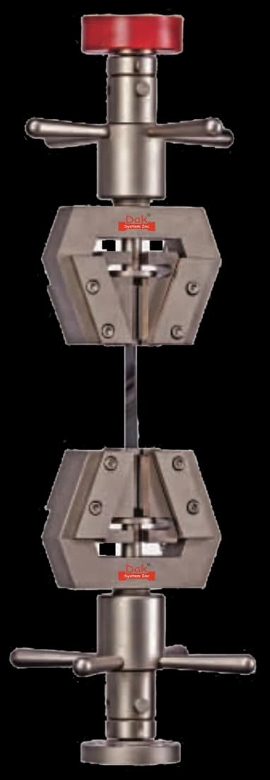
Self-tighteningTJ-15
Universal Parallel Wedge Grips
Self-tightening wedges hold a flat metal adherend squarely. Shims or offset grips keep the load line through the bond, since the two strips lie on different planes.
Specifications
Testing standard
Standard Test Method for Apparent Shear Strength of Single-Lap-Joint Adhesively Bonded Metal Specimens by Tension Loading (Metal-to-Metal)
Written and technically reviewed by Dak System Inc. engineeringLast reviewed
ASTM D1002 measures the apparent shear strength of an adhesive in a single-lap joint. Two metal strips bonded over a short overlap are pulled apart and the peak load is divided by the bonded area. The word apparent is load-bearing: the joint rotates as it loads, so the glue line carries peel as well as shear, and the figure ranks adhesives rather than supplying a design stress.
From the test method to your testing system
Explore the DAK machines already listed for ASTM D1002, then review the grips, measurement and setup requirements below.
 Universal Testing MachineSeries 7200Explore the machine →
 Universal Testing MachineSeries 9000Explore the machine →
01Understand the method
Two flat metal strips are bonded end-to-end so that they overlap by a short defined length, with the adhesive sandwiched in between. The assembled coupon is clamped at each free end in a tensile frame and pulled along its length until the joint ruptures. Only force is recorded. Because the two adherends lie on different planes, the joint rotates slightly as load builds, so the glue line carries peel as well as shear right up to failure.
The result is a single figure: peak load divided by bonded area, reported as an apparent shear strength. The word "apparent" is load-bearing. The number moves with overlap length, adherend thickness and stiffness, and surface preparation, so it ranks adhesives and monitors a bonding process rather than supplying a design allowable. The standard is explicit that treating it as a design stress can lead to product failure, and a separate guide, D4896, exists to explain how far single-lap results can be pushed.
Just as informative is the failure surface. Cohesive failure, with adhesive left on both adherends, says the adhesive's own strength set the limit; interfacial failure, where one face comes away clean, points at degreasing, etching or priming. On a production line that distinction is often the reason the test is run.
02Prepare the specimen and test settings
The standard says plainly that treating this as a design stress can lead to product failure, and a separate guide, ASTM D4896, exists to explain how far single-lap results can be pushed. It is a comparison and a process monitor.
03Build the test setup on a DAK machine
On the standard bond area a flexible sealant failing at a few megapascals ruptures near 0.6 kN, while a structural aerospace epoxy at 40 to 45 MPa reaches 13 to 15 kN. A 10 kN frame covers sealants and general-purpose adhesives; 30 kN is the usual choice for structural work.
The method is written as a load-rate test: shear stress applied at 8.3 to 9.7 MPa per minute (1200 to 1400 psi/min) of shear area, which on the 323 mm² standard bond is about 2.7 to 3.1 kN/min. In crosshead control that is approximately 1.3 mm/min (0.05 in./min). Force accuracy follows E4, the ASTM force-verification practice D1002 references. No extensometer is needed — there is no gauge length here, only a bonded length.
Gripping decides the result. Serrated wedge or pneumatic side-action grips must be aligned so the line of force passes through the centre of the joint, and shims at each specimen end bring the bond line onto the load axis. Elevated- and sub-zero-temperature lap shear are separate methods, so no chamber belongs here.
Self-tightening wedges hold a flat metal adherend squarely. Shims or offset grips keep the load line through the bond, since the two strips lie on different planes.
Specifications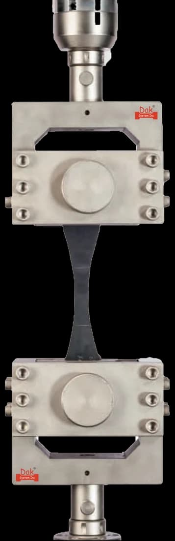
Hydraulic closure where the adherends are thick or the joint strong enough that a manual wedge would slip before the bond failed.
SpecificationsDak verifies against whichever standard the method names, and where a class applies our frames sit a class tighter than it asks.
| The method asks for | Dak supplies | |
|---|---|---|
| Capacity | The standard specimen bonds a 25.4 mm wide lap over a 12.7 mm overlap, giving a 322.6 mm² bond area, so a flexible adhesive at a few MPa fails near 0.6 kN while an aerospace structural epoxy at 40–45 MPa reaches 13–15 kN. A 10 kN frame covers most sealants and general-purpose adhesives; a 30 kN frame is the usual choice for structural work and leaves headroom for the wedge grips. | Load cells from 1 kg to 60 ton on the Series 7200, and 0.5 to 100 kN on the Series 9000 |
| Force accuracy | ASTM E4 | Verified to ASTM E4, and to ISO 7500-1 Class 0.5 |
| Gripping | Self-tightening serrated wedge grips (or pneumatic side-action grips) on a tensile frame, with alignment shims at each specimen end | Our self-tightening serrated wedge grips, with V-jaws for round specimens, built to the specimen |
| Environment | Controlled laboratory atmosphere; elevated- and sub-zero-temperature lap shear are separate methods (D2295 and D2557 respectively), not options within D1002 | 3009 series chambers, −150 °C to +400 °C — temperature only |
04Run the test
05Calculate, report and interpret
τ = P_max / (l × w)
APPARENT, because the stress is not uniform across the overlap. The joint rotates under load and the ends of the glue line carry far more than the middle, so this is an average over a distribution the test does not resolve.
Skipping the alignment shims is the commonest error. The joint already rotates; grip misalignment on top of that drives peel at the overlap ends, and the value drops for reasons unconnected with the adhesive.
Adherend yield is next. If the metal is too thin or too soft for the adhesive under test, the strips yield before the glue line does and the reported stress is a property of the metal. The fix is thicker adherends or a shorter overlap, not a re-run.
Grip damage is the third. Serrated jaws biting hard, thin adherends can notch them at the jaw line and seed a failure there; too little clamping and the coupon walks out under load, leaving a scored tab and a low reading.
Finally, cure state: testing before the adhesive has reached its specified cure shifts results widely while leaving the data looking plausible.
06Compare methods and find answers
| ASTM D1002 | ASTM D903 / D1876 | ASTM D5528 | |
|---|---|---|---|
| Loading | Shear, with peel at the ends | Peel | Opening, Mode I |
| Adherends | Both rigid | At least one flexible | Composite laminate arms |
| Output | Apparent shear strength | Force per width | Fracture toughness, energy per area |
| Design allowable | No | No | Closer — an energy quantity |
All three rank bonds and monitor process. Only the fracture-mechanics route gives a quantity that transfers to a joint of different geometry, which is the reason it exists.
It is the ASTM test for apparent shear strength of adhesives using a single-lap-joint specimen. Two metal strips bonded over a short overlap are pulled until the joint ruptures, and the peak load divided by the bonded area is the reported figure.
Because the stress is not uniform across the overlap. The two adherends lie on different planes, so the joint rotates slightly as load builds and the ends of the glue line carry peel as well as shear — far more stress than the middle. The reported number is an average over a distribution the test does not resolve, and the word apparent is there to stop it being read as a material property.
No, and the standard says so explicitly — treating it as a design stress can lead to product failure. The figure moves with overlap length, adherend thickness and stiffness, and surface preparation, so it does not transfer to a joint of different geometry. ASTM D4896 exists specifically to explain how far these results can be pushed.
Because it tells you what to change. Cohesive failure, with adhesive left on both adherends, means the adhesive's own strength set the limit. Interfacial failure, where one face comes away clean, points at degreasing, etching or priming. On a production line that distinction is often the whole reason the test is run.
Ordinary tensile grips, but with attention to the load line. Because the adherends are offset, the coupon wants to rotate as it loads; shims in the grips or offset jaws keep the line of pull through the bond rather than adding avoidable bending on top of what the geometry already produces.
Because shear stress in a lap joint is not uniform — it peaks at the two ends of the overlap and dips in the middle. The longer the overlap, the more pronounced that peaking becomes, so the average stress at failure falls even though the joint carries more total load. A short, fixed overlap keeps the non-uniformity comparable between specimens, which is what makes the apparent strength useful for comparison.
More than almost anything else, and it is the usual reason two laboratories disagree about the same adhesive. Degreasing, abrasion, etching and priming all change how well the adhesive wets and keys to the metal, and a joint that fails cleanly at the interface is usually reporting on the preparation rather than the adhesive. The preparation must be specified and recorded in full for a result to mean anything.
Discuss your specimen, test requirements and reporting needs with DAK engineering.
This page describes the method as practised. The governing text is the current edition from the issuing body. Tell us what you are testing and we will answer with the machine, the fixture and a quotation.