
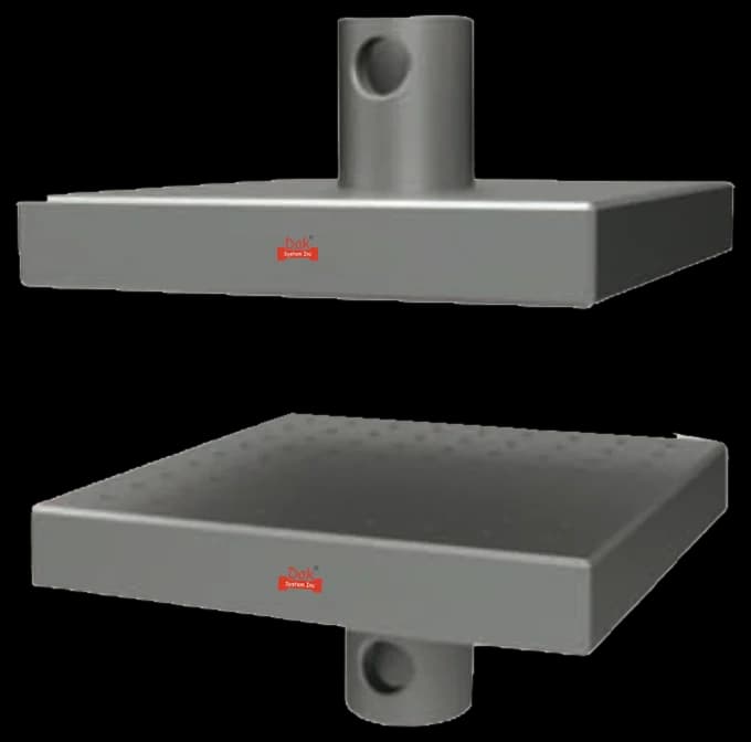
5 to 400 kNTJ-125
Direct Compression Fixture
The strip is loaded end-on by a compression platen, so the frame does a straightforward compression job while the jig prevents buckling.
Specifications
Testing standard
Standard Test Method for In-Plane Shear Strength of Reinforced Plastics (Withdrawn 2024)
Written and technically reviewed by Dak System Inc. engineeringLast reviewed
ASTM D3846 measured in-plane shear strength of reinforced plastics. A narrow strip with two offset slots, each cut to about half the thickness, is compressed end-on inside an anti-buckling jig, so the only continuous material left is a short ligament that fails in shear along the plane joining the slot roots. The method has been withdrawn, but specifications still cite it.
From the test method to your testing system
Explore the DAK machines already listed for ASTM D3846, then review the grips, measurement and setup requirements below.
 Universal Testing MachineSeries 7200Explore the machine →
 Universal Testing MachineSeries 9000Explore the machine →
01Understand the method
A narrow strip of reinforced thermosetting sheet has two parallel slots machined across it, one on each face, offset along the length and each cut to roughly half the thickness. The strip is stood on end inside a jig that clamps its flat faces to stop it buckling, then compressed along its length. Because the two slots overlap through the thickness, the only continuous material left between them is a short ligament, and that ligament fails in shear along the plane joining the slot roots.
The method returned one figure: in-plane shear strength, peak compressive force divided by specimen width times the length of the failed ligament. For randomly reinforced and nonparallel-fibre laminates it described how well resin and reinforcement architecture resisted shearing along a plane through the thickness — the property that limits how much load a bolt bearing or a bonded overlap can hand into the laminate, and the one most sensitive to how well the resin has wetted a randomly oriented mat, which has no continuous fibre path once the resin lets go.
The method existed because those materials could not be tested satisfactorily by the short-beam method: a random mat has no clean interlaminar plane for a short beam to shear along. That matters for anyone leaving D3846: the short-beam standard is not the migration route.
02Prepare the specimen and test settings
The method is withdrawn. Where a specification still names it, the honest position is to run it as written and record that it is a withdrawn method — and to raise D5379 or a rail shear method for any new work.
03Build the test setup on a DAK machine
What follows is historical sizing, offered for judging archived data — not a recommendation to run a withdrawn method.
The sheared area was strip width times slot spacing, around 81 mm². At shear strengths of roughly 15 to 45 MPa for random-fibre thermosets, failure fell between about 1.2 and 3.7 kN. Modest forces, but the frame had to be compression-capable and stiff, since it also drove the anti-buckling jig and overcame the friction in it; 10 to 50 kN was the usual choice. Force accuracy would follow the general ASTM force-verification practice, inferred from the universal ASTM requirement rather than confirmed against the withdrawn edition's reference list.
Crosshead rate was 1.3 mm/min (0.05 in/min) in compression, held to failure. No strain was measured and no extensometer was fitted; the slot spacing served as the sheared length, not as a gauge length.
The fixture was the supporting jig from the compression method for rigid plastics — ground side plates clamped against the specimen faces by bolts tightened to a specified torque. Its job was to stop the slender coupon buckling before it sheared, and bolt torque was the balance point: too loose and the specimen buckles, too tight and the plates carry load through friction, reading in the force record as strength the material does not have.
The strip is loaded end-on by a compression platen, so the frame does a straightforward compression job while the jig prevents buckling.
Specifications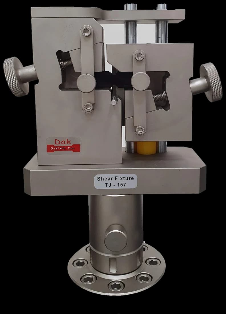
The anti-buckling jig clamps the flat faces and prevents out-of-plane movement — alignment is a property of the fixture here, and the slot tooling itself is made to the method's geometry.
SpecificationsDak verifies against whichever standard the method names, and where a class applies our frames sit a class tighter than it asks.
| The method asks for | Dak supplies | |
|---|---|---|
| Capacity | The sheared area is the 12.7 mm specimen width by the 6.4 mm notch spacing, about 81 mm², so a random-fibre thermoset laminate at 15–45 MPa failed between roughly 1.2 kN and 3.7 kN. Modest force, but the frame had to be compression-capable and stiff enough to drive the D695 supporting jig; 10–50 kN was the usual size. This is historical sizing only — the method is withdrawn. | Load cells from 1 kg to 60 ton on the Series 7200, and 0.5 to 100 kN on the Series 9000 |
| Force accuracy | ASTM E4 | Verified to ASTM E4, and to ISO 7500-1 Class 0.5 |
| Gripping | ASTM D695 anti-buckling supporting jig — lateral side plates and clamping bolts, loaded on the specimen ends through compression platens | Our compression anvils, built to the specimen |
| Environment | Controlled laboratory atmosphere; exact figures not recoverable from public sources for the withdrawn edition | 3009 series chambers, −150 °C to +400 °C — temperature only |
04Run the test
05Calculate, report and interpret
τ = P_max / (w × l)
The ligament length is MEASURED ON THE FAILED SPECIMEN rather than taken from the drawing, because slot machining tolerances land directly on it.
Bolt torque drift is the classic. The clamping bolts were meant to be set to a defined torque and re-checked; a laboratory tightening them by feel produced a slow walk in results that read convincingly as a material trend.
Slot machining was the second. If the two cuts did not both reach mid-thickness, the ligament was thicker or thinner than the calculation assumed and the strength scaled with the error. A blunt cutter left a burr at the root that started the fracture early.
Third, the fracture leaving the intended plane. In a random mat the crack follows the reinforcement rather than the geometry, so a surface running diagonally or breaking out to a face means the failed length was not the slot spacing and the arithmetic divides by the wrong number.
Fourth, easiest to miss, is buckling inside the jig — a buckled coupon still gives a peak force.
06Compare methods and find answers
| ASTM D3846 (withdrawn) | ASTM D5379 V-notch | ASTM D2344 short beam | |
|---|---|---|---|
| Status | Withdrawn | Current | Current |
| Stress state | Shear on a machined ligament | Nearly pure shear at the notch section | Complex, under a nose |
| Gives modulus | No | Yes, with gauges | No |
| Suits | Randomly reinforced laminates | Most laminates | Fast screening |
For new work, D5379 is the current route to in-plane shear and gives a modulus as well as a strength. D3846 is documented here because older specifications and datasheets still cite it, and a laboratory asked to reproduce a legacy result needs to know what was done.
It was the ASTM method for in-plane shear strength of reinforced plastics. A narrow strip with two offset slots, each about half the thickness, is compressed end-on in an anti-buckling jig so the short ligament between the slot roots fails in shear. The method has been withdrawn, but older specifications still cite it.
Only where a specification or a legacy comparison requires it, and then the report should say plainly that it is a withdrawn method. For new work ASTM D5379 is the current route to in-plane shear and gives a modulus as well as a strength, which D3846 never did.
Because a narrow strip compressed along its length would buckle long before the ligament sheared, and the test would measure column stability rather than shear. The jig clamps the flat faces so the strip cannot bow, forcing failure into the plane the slots define.
Because slot machining tolerances land directly on it. The ligament length is the divisor in the calculation, so a nominal figure from the drawing carries whatever error the machining introduced. Measuring the actual failure plane after the test removes it.
Randomly reinforced and nonparallel-fibre laminates, where there is no continuous fibre path once the resin lets go. It described how well the resin and the reinforcement architecture resisted shearing through the thickness — the property that limits how much load a bolt bearing or a bonded overlap can hand into such a laminate.
Nothing replaced it directly, which is part of why it is still encountered. Where in-plane shear properties are needed, ASTM D5379 V-notched beam shear and ASTM D7078 V-notched rail shear are the current methods and produce cleaner shear states. Where a legacy specification still calls for D3846, the sensible course is to run it, report it as a withdrawn method, and generate a current-method result alongside.
So that the shear plane is forced to run through the ligament between them rather than anywhere the material would prefer. Two offset slots, each about half the thickness deep, leave a defined block of material that must shear for the specimen to fail. If the slots are too shallow the specimen fails elsewhere; too deep and the ligament is damaged before loading, which is why the depth is checked on the failed specimen rather than assumed.
Discuss your specimen, test requirements and reporting needs with DAK engineering.
This page describes the method as practised. The governing text is the current edition from the issuing body. Tell us what you are testing and we will answer with the machine, the fixture and a quotation.