
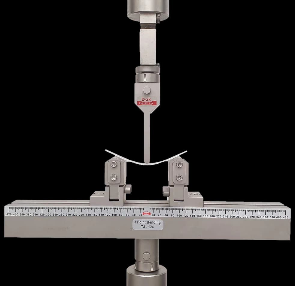
Adjustable spanTJ-124
Three Point Bend Fixture
Two cylindrical supports on a graduated beam with a central loading nose, and a span that resets from 25 to 300 mm as the specimen depth changes.
Specifications
Testing standard
Standard Test Methods for Flexural Properties of Unreinforced and Reinforced Plastics and Electrical Insulating Materials
Written and technically reviewed by Dak System Inc. engineeringLast reviewed
ASTM D790 measures how stiff and how strong a plastic is in bending. A rectangular bar rests on two supports and a loading nose presses down on the middle of the span at a controlled rate until the bar breaks or reaches 5 % outer-fibre strain. It reports flexural strength, flexural stress at a chosen point, outer-fibre strain and flexural modulus — the stiffness figure used for wall-thickness calculations and finite-element work.
From the test method to your testing system
Explore the DAK machines already listed for ASTM D790, then review the grips, measurement and setup requirements below.
 Universal Testing MachineSeries 7200Explore the machine →
 Universal Testing MachineSeries 9000Explore the machine →
01Understand the method
A rectangular bar of plastic is laid flatwise across two parallel cylindrical supports; nothing is gripped or clamped. A loading nose descends onto the midpoint of the span and bends the bar at a constant rate while force and midspan deflection are recorded. The run ends at rupture or at 5.0 % outer-fibre strain, whichever comes first, so a ductile grade may finish the test unbroken.
The method reports flexural strength, flexural stress at any chosen point on the curve, maximum outer-fibre strain and flexural modulus, taken from the initial straight portion of the curve. Modulus is the stiffness figure that feeds wall-thickness calculations and finite-element modelling, and it separates unfilled grades from filled ones. Flexural strength serves lot release on moulding compounds and electrical insulating materials. Because the outer fibre carries the peak stress, the result is sensitive to moulded skin quality, which makes it useful in moulding investigations.
02Prepare the specimen and test settings
Nothing is gripped in this test, so the specimen and the span between the supports are what define it. Get the span wrong and every number in the batch is wrong with it.
Depth drives the span, the rate and both results. Measure the bar you are about to test rather than trusting the nominal thickness, and reset the span whenever the thickness changes.
D790 does not name a crosshead speed. It names a strain rate, and the speed is calculated from the specimen you actually have — which is why two laboratories testing the same grade at different thicknesses correctly run at different speeds.
R = Z L² / (6 d)
Span appears squared, so a 32:1 span runs four times faster than a 16:1 span on the same bar.
The rate follows the specimen. Changing the thickness or the span ratio changes the correct speed, and a speed carried over from the previous job is one of the most common sources of a wrong modulus.
03Build the test setup on a DAK machine
Force demand is low. Most moulded bars fail between roughly 20 N and 1 kN, so a frame of around 2 kN carries almost all D790 work, provided the load cell resolves cleanly down to about 10 N rather than merely reaching the top of its range. Thick laminated thermoset bars run at 32:1 or 40:1 can call for several kilonewtons. Force indication must be verified to ASTM E4.
Rate is defined as a strain rate and converted to crosshead speed by R = ZL²/6d. Procedure A runs at 0.01 mm/mm/min and Procedure B ten times faster at 0.10 mm/mm/min, giving about 1.4 and 13.7 mm/min for the 3.2 mm bar on its 51.2 mm span. Supports must be span-adjustable: 16:1 as standard, 32:1 or 40:1 for high-strength reinforced composites that would otherwise shear, and up to 60:1 where modulus is the object.
Modulus requires a Type II deflectometer classified to ASTM E83 Class B-2; Class C is accepted for the other reported values, and Type I crosshead-position measurement is also permitted. The fixture is a three-point rig — two cylindrical supports and a central loading nose, 5.0 ±0.1 mm radii unless otherwise specified. For bars 3.2 mm deep or more, the support radius may be raised to 1.6 times the depth and the nose radius to 4 times, so the sides of the nose do not foul the specimen. Supports and nose must be parallel, with the bar centred between them. Testing takes place in the D618 atmosphere; other temperatures apply only where the material specification calls for them.
Two cylindrical supports on a graduated beam with a central loading nose, and a span that resets from 25 to 300 mm as the specimen depth changes.
SpecificationsDak verifies against whichever standard the method names, and where a class applies our frames sit a class tighter than it asks.
| The method asks for | Dak supplies | |
|---|---|---|
| Capacity | Most moulded plastic bars fail somewhere between roughly 20 N and 1 kN, so a modest frame with a well-matched low-capacity load cell covers almost all D790 work; thick laminated thermoset bars tested at 32:1 or 40:1 can demand several kilonewtons. | Load cells from 1 kg to 60 ton on the Series 7200, and 0.5 to 100 kN on the Series 9000 |
| Force accuracy | ASTM E4 | Verified to ASTM E4, and to ISO 7500-1 Class 0.5 |
| Strain measurement | An extensometer to ASTM E83 Class B-2 (Type II deflectometer, minimum for modulus; Class C acceptable for other values). Type I crosshead-position measurement is also permitted; the accuracy class required for Type I is unknown., gauge length n/a — flexure has no gauge length; the governing dimension is the support span, 51.2 mm for the standard 3.2 mm bar at 16:1 (adjustable) | Certified to ASTM E83 and ISO 9513 Class 1 — non-contact video, clip-on and high-elongation |
| Gripping | Adjustable three-point bend rig — two cylindrical supports plus a central loading nose, 5 mm radii | Our bend fixtures, built to the specimen |
| Environment | Ambient: Practice D618 standard laboratory atmosphere, 23 ±2 degC and 50 ±10 % RH; other temperatures only where the material specification calls for them | 3009 series chambers, −150 °C to +400 °C — temperature only |
04Run the test
The sequence below is the method as practised. It follows the standard's requirements but the ordering and the checks are ours.
The two steps most often skipped are measuring each bar and resetting the span. Both are silent: the test runs, a curve appears, and the numbers are wrong in a way nothing on the screen reveals.
05Calculate, report and interpret
Three equations carry the whole method. They are reproduced here with every term defined, so the page is usable without the standard open beside it — but the governing text is always the current edition.
σf = 3 P L / (2 b d²)
Flexural strength is this equation evaluated at maximum force. Where deflection exceeds about 10 % of the span, D790 gives a large-deflection correction and the plain equation over-reads.
εf = 6 D d / L²
Rearranged, this is what fixes the 5 % cut-off as a deflection the machine can watch for.
EB = L³ m / (4 b d³)
Depth is cubed here. Modulus is the most dimension-sensitive number the method produces, and the reason the bar is measured rather than assumed.
A flexural result travels badly without its conditions. These are the entries that make a number reproducible by somebody else.
Four failures recur. A loading nose of small radius indents a soft or thin bar, so local crush is counted as deflection and modulus reads low. A reinforced laminate run at 16:1 fails in shear between the plies instead of in tension, and the number recorded is not a flexural strength at all. Ductile grades reach the 5.0 % strain cut-off intact, leaving no strength value to report. And a span left at a previous setting, or taken from nominal rather than measured depth, biases every result in the batch.
06Compare methods and find answers
One method, two rates, and the choice belongs to the material rather than to the schedule.
| Procedure A | Procedure B | |
|---|---|---|
| Strain rate | 0.01 mm/mm/min | 0.10 mm/mm/min |
| Rate, 3.2 mm bar at 16:1 | ≈ 1.4 mm/min | ≈ 13.7 mm/min |
| Intended for | Materials that break at comparatively small deflections | Materials that undergo large deflections before breaking |
| Use for flexural modulus | Yes | Not the usual choice |
| Typical subjects | Filled and reinforced grades, rigid thermosets | Unfilled ductile thermoplastics |
Results from the two procedures are not interchangeable. Plastics are rate-sensitive, and the faster run generally returns the higher strength.
These four all bend a bar, and none of their results may be pooled with another's.
| ASTM D790 | ISO 178 | ASTM D6272 | ASTM D7264 | |
|---|---|---|---|---|
| Loading | Three-point | Three-point | Four-point | Three- or four-point |
| Subject | Plastics and electrical insulation | Plastics | Plastics and electrical insulation | Polymer-matrix composites |
| Reference specimen | 127 × 12.7 × 3.2 mm | 80 × 10 × 4 mm | As D790 | As specified for the laminate |
| Span ratio | 16:1 default | 16 × thickness | 16:1 default | 32:1 |
| Rate basis | Strain rate, converted | Fixed speed, commonly 2 mm/min | Strain rate, converted | 1.0 mm/min fixed |
| Modulus taken as | Tangent, initial slope | Secant, between fixed strains | Tangent | Chord, over a defined range |
ISO 178 is the one mistaken for D790 most often. The geometry looks identical, but the specimen, the rate basis and the modulus definition all differ — and the support radius is the detail most often missed when a D790 rig is reused for ISO work. Numbers from the two cannot be compared, and must never be averaged together.
It is the ASTM test method for the flexural properties of unreinforced and reinforced plastics and electrical insulating materials. A rectangular bar is supported near its ends and loaded at the centre of the span until it breaks or reaches 5 % outer-fibre strain, and the method reports flexural strength, flexural stress, outer-fibre strain and flexural modulus.
The recommended bar for moulding materials is 127 × 12.7 × 3.2 mm, tested flatwise. Bars machined from sheet take the sheet's own thickness as their depth. Whatever the depth, the support span is set to sixteen times it, and specimens deeper than 3.2 mm must be no wider than a quarter of the span.
Sixteen to one is the default, giving a 51.2 mm span on the 3.2 mm reference bar. Reinforced materials that would fail in interlaminar shear at 16:1 are run at 32:1 or 40:1, and spans as long as 60:1 are used where modulus is the object. The ratio is chosen so the bar fails in tension on its outer fibre rather than in shear between its plies.
The standard specifies a strain rate rather than a speed, and the crosshead rate is calculated from R = ZL²/6d. Procedure A runs at 0.01 mm/mm/min and Procedure B at 0.10 mm/mm/min, which for the 3.2 mm bar on its 51.2 mm span works out at roughly 1.4 and 13.7 mm/min. Change the thickness or the span and the correct speed changes with them.
Only the rate, but it decides which materials each suits. Procedure A is ten times slower and is intended for materials that break at comparatively small deflections; it is also the procedure used for flexural modulus. Procedure B suits materials that deflect a long way before breaking. Because plastics are rate-sensitive the two do not give the same answer, so the report has to say which was used.
Because beyond that point the simple beam equations stop describing what the bar is doing — the deflection is large enough that the geometry itself has changed. Many ductile grades never break within that limit, and for those the correct output is the flexural stress at 5 % strain rather than a flexural strength, which does not exist for that material under this method.
They share the three-point geometry and nothing else that matters. ISO 178 uses an 80 × 10 × 4 mm bar, derives its rate differently, and takes modulus as a secant between two fixed strains where D790 takes the initial tangent. Support radii differ too, which is the detail most often overlooked when one fixture is used for both. Results from the two are not comparable and should never be averaged together.
For flexural modulus, yes — the standard calls for a Type II deflectometer classified to ASTM E83 Class B-2, measuring midspan deflection directly. For flexural strength and stress at a given strain, Class C is accepted and crosshead position may be used. Taking modulus from crosshead travel alone includes the machine's own compliance and the indentation of the nose into the bar, and reads low as a result.
Less than most people expect. Moulded bars usually fail between about 20 N and 1 kN, so a 2 kN frame covers nearly all routine D790 work — provided the load cell resolves cleanly at the bottom of that range rather than merely reaching the top of it. Thick laminated thermosets run at 32:1 or 40:1 can demand several kilonewtons. Force indication must be verified to ASTM E4.
Yes. Both are bending tests on the same frame at similar forces, and the difference is the fixture — three-point for D790, four-point for D6272. A single universal testing machine with interchangeable bend fixtures covers both, along with the tensile and compression methods that usually sit beside them in the same laboratory.
At least five. Anisotropic materials need a set in each principal direction, so ten in total. The report carries the mean and the standard deviation, and any specimen discarded for a visible flaw on the tension face has to be recorded as discarded rather than quietly replaced.
Discuss your specimen, test requirements and reporting needs with DAK engineering.
This page describes the method as practised. The governing text is the current edition from the issuing body. Tell us what you are testing and we will answer with the machine, the fixture and a quotation.