
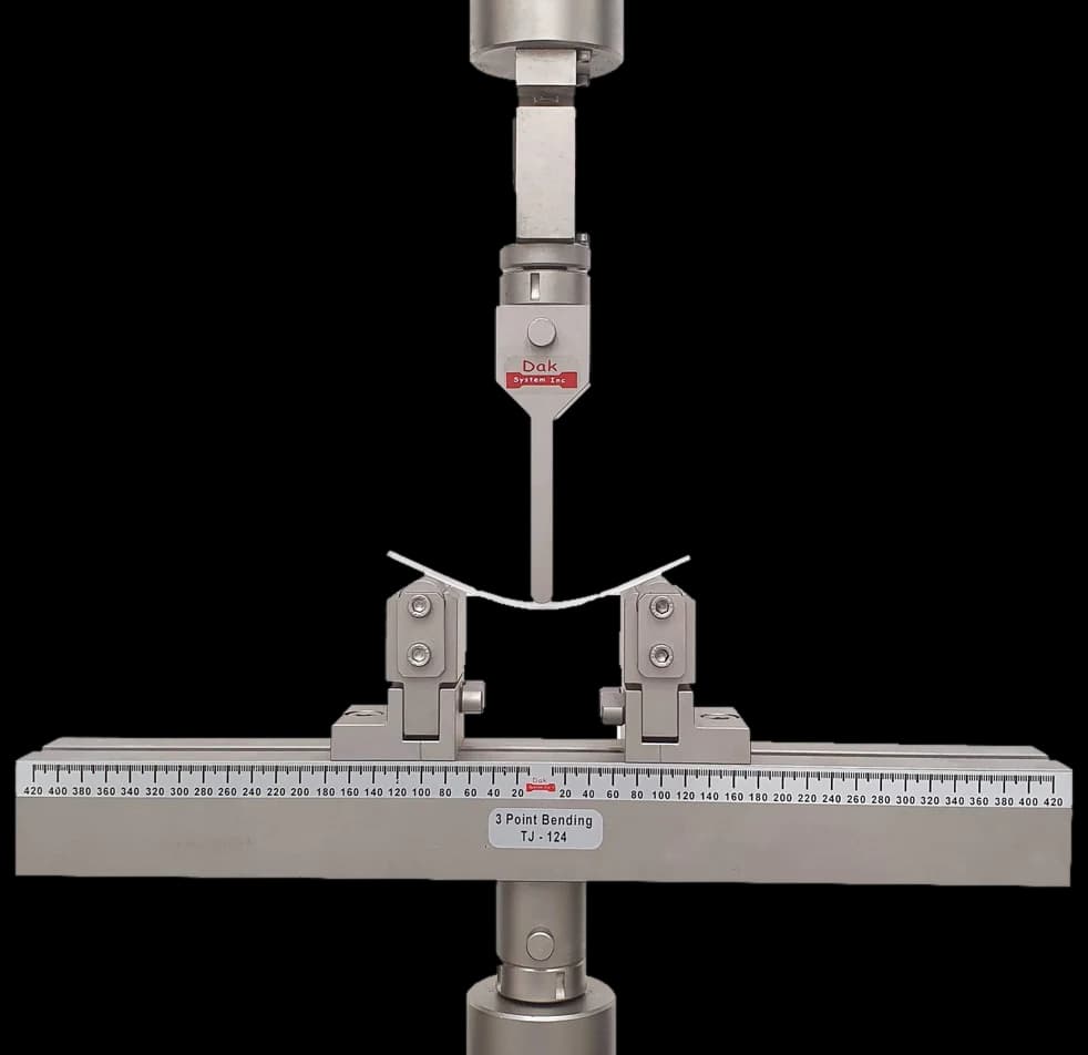
Adjustable spanTJ-124
Three Point Bend Fixture
A three-point bend fixture with adjustable span and the roller diameters the method specifies — span-to-depth ratio is set on the fixture, not assumed.
Specifications
Testing standard
Standard Test Method for Guided Bend Test for Ductility of Welds
Written and technically reviewed by Dak System Inc. engineeringLast reviewed
ASTM E190 is the guided bend test for weld ductility. A coupon is forced into a jig of defined radius so that the bend geometry is imposed rather than found, and the convex surface is then examined for cracks and open defects against the governing code's acceptance limit.
From the test method to your testing system
Explore the DAK machines already listed for ASTM E190, then review the grips, measurement and setup requirements below.
 Universal Testing MachineSeries 7200Explore the machine →
 Universal Testing MachineSeries 9000Explore the machine →
01Understand the method
A coupon is cut transverse to a welded joint, its reinforcement removed flush with the base metal and its edges rounded. It is then placed in a guided bend jig — a plunger of specified radius forced into a die of specified opening, or a wrap-around former — with the surface of interest facing the tension side, and bent in one movement to the full angle. The convex surface is afterwards examined under magnification for cracks and open defects, their length judged against the acceptance limit in the code that called up the test.
Strictly nothing is measured; the outcome is a judgement on a surface. What the method contributes is comparability. In a free bend the specimen finds its own radius according to how it work-hardens, so two laboratories bending nominally identical coupons impose different strains and reach different verdicts. Guiding the bend fixes the geometry, which is why the plunger radius and die opening belong in the report rather than any force. Weld ductility is then a defensible finding rather than an impression. It is used wherever a welding procedure or a welder has to be qualified before production starts — pressure vessels under ASME rules, structural steelwork under the AWS codes, pipelines, heavy plant — and in production testing, where coupons welded alongside the real joints are bent to confirm that what was qualified in the laboratory is still being achieved on the shop floor. In failure investigation it runs the other way round, to establish whether a joint that cracked in service was ductile enough to begin with.
02Prepare the specimen and test settings
The word guided is the whole point. The jig imposes the curvature, so two laboratories bending the same material get the same strain.
Nothing here is graded. The coupon meets the code's crack limit or it does not, and the number that matters in the report is the plunger radius rather than any force.
03Build the test setup on a DAK machine
Enough force to complete the bend — commonly five to a hundred kilonewtons depending on section and former size — with the stroke to reach the full angle without repositioning, and a jig holding the plunger radius and die opening the code requires. Force accuracy matters less here than in most methods, since nothing is calculated from the load; what the frame needs is the stability to drive the plunger straight and the travel to finish the bend in one movement.
E190 sets no rate of plunger travel, and does not need one: any convenient means may be used so long as the motion is steady and free of significant lateral movement. The severity is fixed by the jig instead. In the standard's own jig figure the plunger is 4t wide with a radius of 2t, the die opening is 6t + 3.2 mm and the shoulders are radiused 3t + 1.6 mm, t being the coupon thickness — so a 9.5 mm coupon is bent by a 38 mm plunger of 19 mm radius into a 60 mm opening. Work the outer-fibre strain out from those numbers, ε = t / (2r + t), and that coupon is being asked for about 20 % elongation. The end of the bend is geometric too: force is applied until the specimen conforms to a U-shape and a 3.2 mm diameter wire will no longer pass between it and the die. Those figures and the code's crack-length limit are what a report has to carry. Crosshead speed is not one of them.
A three-point bend fixture with adjustable span and the roller diameters the method specifies — span-to-depth ratio is set on the fixture, not assumed.
Specifications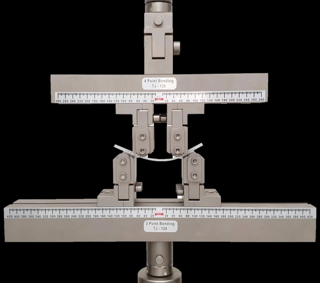
Four-point loading where the specification calls for it, putting a length of the specimen under constant moment rather than concentrating it under one nose.
SpecificationsDak verifies against whichever standard the method names, and where a class applies our frames sit a class tighter than it asks.
| The method asks for | Dak supplies | |
|---|---|---|
| Capacity | Moderate to high — typically 5 to 100 kN with the former and section | Load cells from 1 kg to 60 ton on the Series 7200, and 0.5 to 100 kN on the Series 9000 |
| Force accuracy | unknown — ASTM E4 is not among this method's referenced documents, which name no force-verification standard and no accuracy class | ISO 7500-1 Class 0.5 — the method sets no class of its own |
| Gripping | Guided bend jig — a plunger of specified radius forced into a die, or a wrap-around former | Our bend fixtures, built to the specimen |
| Environment | 23 ± 2 °C standard laboratory atmosphere | 3009 series chambers, −150 °C to +400 °C — temperature only |
04Run the test
05Calculate, report and interpret
Approximately t / (2R + t)
Not reported by this method, but it is why a tighter plunger radius on a thicker coupon is a much more severe test than the radius alone suggests.
Maximum permitted crack length on the convex surface
Taken from the governing construction code, not from E190 itself.
Using a larger plunger radius than the code specifies has the greatest consequence, because it quietly makes the test easier while producing a report that looks identical; recording the jig geometry is the defence. Sharp coupon edges generate corner tears indistinguishable from real defects. Stopping mid-bend leaves a witness mark on the very surface being examined. Inspecting by eye rather than under magnification misses fine root cracks a few millimetres long, the defect the test exists to find. And reporting a pass without naming the code the jig geometry came from leaves a reader unable to tell whether the coupon met a demanding requirement or a lenient one.
06Compare methods and find answers
| ASTM E190 | ISO 5173 | |
|---|---|---|
| Family | ASTM | ISO |
| Jig | Plunger and die, or wrap-around | Former between rollers, or wrap-around |
| Bend severity from | The governing construction code | The material's specified elongation |
| Framework | ASME BPVC Section IX, AWS codes | ISO 15614 procedure qualification |
The same examination in two families. Which applies is contractual, and a coupon bent to one does not automatically satisfy the other, because the geometry that sets severity is drawn from different sources.
It is the ASTM guided bend test for the ductility of welds. A coupon cut from a welded joint is forced into a jig of specified radius so that the bend geometry is imposed rather than left to the specimen, and the stretched convex surface is then examined for cracks against the governing code's acceptance limit.
That the curvature is set by the jig, not by the material. In a free bend the specimen finds its own radius, which depends on how it work-hardens, so two laboratories bending nominally identical coupons impose different strains. A plunger and die of fixed dimensions removes that variable, which is what makes the results comparable at all.
From the governing construction code — ASME BPVC Section IX, an AWS structural code, or the contract — chosen from the base material. E190's own jig figure gives the default proportions: a plunger 4t wide with a radius of 2t into a die opening of 6t + 3.2 mm, so a 9.5 mm coupon takes a 38 mm plunger of 19 mm radius in a 60 mm opening, which is about 20 % outer-fibre elongation. It is not a free choice, because it is the single parameter that fixes how severe the test is. A larger radius makes the coupon easier to pass while leaving no trace in the report unless the geometry is recorded, which is why it is recorded.
Whatever the code specifies. Root bends put the weld root in tension and find incomplete penetration, the most common serious joint defect. Face bends stretch the cap. Side bends take a through-thickness slice and bend it on edge, exposing every weld pass at once, which is why they are used on thicker sections and are the most searching of the three.
Usually judged separately. Most codes distinguish between a crack in the body of the weld, which indicates a real soundness problem, and a tear at the specimen edge, which often originates from a machining corner or an inclusion at the cut face rather than the joint. The two carry different limits, so the report should say which was found.
Because stopping and restarting can leave a witness mark on the convex surface that is difficult to distinguish from a genuine crack once the coupon is out of the jig. Since the examination afterwards is the entire test, anything that introduces an ambiguous feature onto the surface being examined costs the coupon.
They answer different questions and are run together. A transverse tensile coupon establishes that the joint carries load, but it can pass a weld containing a lack of fusion if enough sound metal remains. Bending forces one surface into large tension so that such a defect opens into a visible crack. Procedure qualification normally requires both.
Discuss your specimen, test requirements and reporting needs with DAK engineering.
This page describes the method as practised. The governing text is the current edition from the issuing body. Tell us what you are testing and we will answer with the machine, the fixture and a quotation.