

Testing standard
ASTM F1717 Spinal Implant Construct Testing in a Vertebrectomy Model
Standard Test Methods for Spinal Implant Constructs in a Vertebrectomy Model
Written and technically reviewed by Dak System Inc. engineeringLast reviewed
ASTM F1717 tests spinal implant constructs in a vertebrectomy model. Anchors, rods and connectors are assembled into two polymer blocks separated by a gap standing in for a removed vertebral body, and hinged joints turn axial machine force into a bending moment. Four methods follow: compression bending, tension bending, torsion, and compression bending fatigue.
At a glance
- Test type
- Fatigue — a load is applied over and over until something fails
- Published by
- ASTM
- Edition
- F1717-21
- Runs on
- Fatigue Tester
From the test method to your testing system
Explore DAK equipment for ASTM F1717, then review the specimen and setup requirements below.
 Fatigue Testing MachineFatigue TesterExplore the machine →
Jump to a specific section
01Understand the method
What the test does
The construct — anchors, longitudinal rods and any connectors — is assembled as the manufacturer intends into two polymer blocks separated by a gap standing in for a removed vertebral body. The blocks connect to the machine through hinged rod-end joints, so force along the machine axis reaches the construct as a bending moment set by the block geometry. Four methods use that arrangement: the gap is closed in compression, opened in tension, twisted about the construct axis, or cycled in compression until the construct fails or reaches run-out.
What it measures, and why it matters
The static methods give a load-displacement or torque-rotation curve, from which stiffness, the yield point and the ultimate load are taken; compression bending runs out to roughly 20 mm of travel and torsion to about 60 degrees of rotation. Those figures say how much bending or twisting the construct carries before it takes a permanent set — the point at which surgical alignment is lost. The fatigue method reports cycles endured at a given load; the load survived to run-out is what most work turns on, since a construct must last until bone fuses across the gap. The standard is explicitly comparative: it sets no level a construct must reach, so a result means something only beside another from the same model.
02Prepare the specimen and test settings
The construct, not a coupon
- What is tested
- The assembled construct as the manufacturer intendsAnchors, longitudinal rods and any connectors — the system, not its parts.
- Blocks
- Two polymer blocks with a gap betweenThe gap stands in for a removed vertebral body. It is the worst case: nothing anterior shares the load.
- Connection
- Hinged rod-end jointsSo axial machine force reaches the construct as a bending moment set by the block geometry rather than as pure compression.
- Four methods
- Compression bending, tension bending, torsion, fatigue
- Not a clinical prediction
- A comparisonThe model is deliberately severe and deliberately simplified — it ranks constructs and screens designs, it does not predict in-vivo life.
Static and dynamic
- Static methods
- Ramped to failure
- Fatigue
- Cycled in compression bendingTo construct failure or to a declared run-out.
- Run-out
- Declared in advanceCommonly five million cycles for spinal hardware. Deciding afterwards is how a programme becomes unusable.
- Frequency
- Chosen so heating and inertia stay negligible
03Build the test setup on a DAK machine
What the machine must be capable of
Capacity is close to the wrong question: the method specifies fixture geometry and a load protocol, and forces follow from the construct bolted into the blocks. Lumbar and thoracolumbar pedicle screw constructs reach ultimate compression bending loads of roughly 0.6 to 2.0 kN, and cycling runs at fractions of that, so most fatigue work sits between a few hundred newtons and about 1.5 kN — a 5 kN dynamic frame covers it with headroom. Cervical constructs sit an order of magnitude lower, where low-force resolution matters more than capacity.
The static methods are slow — up to 25 mm/min in bending, commonly 30 to 60 degrees per minute in torsion — so rate sensitivity is not the issue; control quality at low speed is. Fatigue is a different machine: force-controlled sinusoidal compression-compression cycling at a load ratio of ten or greater, at no more than about 5 Hz, to a run-out of five million cycles. That is some eleven and a half days of unattended running per specimen, so cycle counting and automatic failure detection matter as much as the actuator.
One method is torsion, in angular-displacement control, which a single-axis fatigue frame cannot run: torsional or biaxial capability is needed. Nothing is instrumented on the construct itself, because the fixture is the test: the hinged joints must move freely, since friction there changes the effective moment arm and every number reported with it. Testing is dry and ambient by default, with saline at body temperature where the implant materials warrant it.
The static rates, load ratio and run-out count come from testing laboratories rather than the purchased text; the 5 Hz maximum is ASTM's own recommended figure for cycling in saline or simulated body fluid. Which force-verification practice the current edition names could not be confirmed publicly.
The machine this method needs
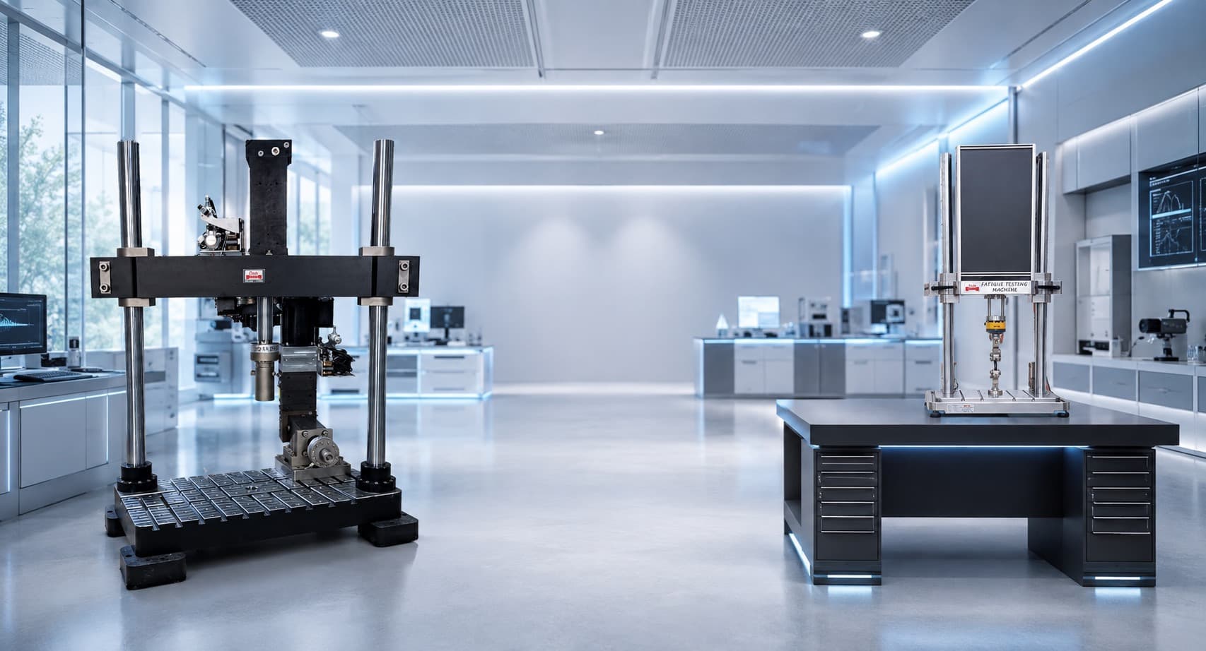
Running ASTM F1717 on the Fatigue Tester
A fatigue frame is judged on whether it holds amplitude at frequency, not on peak load, so the figures that matter here are the cycling ones.
| The method asks for | Dak supplies | |
|---|---|---|
| Load & frequency | No capacity is prescribed — the standard is fixture geometry plus a load protocol. Lumbar and thoracolumbar pedicle screw constructs typically reach ultimate compression bending loads of roughly 0.6–2.0 kN, and fatigue levels are then stepped down from that ultimate at about 75 %, 50 % and 25 %, so most of the cycling happens between a few hundred newtons and about 1.5 kN. A 5 kN dynamic frame covers the work with headroom; cervical constructs sit an order of magnitude lower and reward good low-force resolution. | Load up to 500 kN at up to 100 Hz, 60 mm actuator stroke with travel resolution up to 0.1 µm |
| Load accuracy | unknown | ±0.5% of reading |
| Gripping | Paired single-use UHMWPE test blocks bridging a simulated vertebrectomy gap, loaded through hinged rod-end joints | Grips built to the specimen, with alignment held through the cycle |
| Environment | Dry ambient laboratory conditions by default; simulated body fluid or saline at body temperature where the implant materials warrant it, which is where the 5 Hz frequency cap bites | 3009 series chambers, −150 °C to +400 °C — temperature only |
04Run the test
How the test runs
- Assemble the construct into the polymer blocks exactly as the manufacturer instructs.
- Set the gap representing the removed vertebral body.
- Connect the blocks to the machine through hinged rod-end joints.
- Declare the failure criterion and the run-out count before starting.
- For static methods, ramp to failure and record load against displacement.
- For fatigue, cycle in compression bending at the chosen load amplitude.
- Continue to construct failure or to run-out.
- Record where and how the construct failed — screw, rod, connector or block.
- Repeat at several loads to establish the run-out load.
Record the failure location every time. A construct that fails at the screw and one that fails at the rod have the same number and quite different design implications.
See the machine
05Calculate, report and interpret
What comes out
k = slope of the elastic portion of the load–displacement curve
How much the construct deflects per unit load, as assembled.
Taken from the static curves
Reported as loads or moments for the construct rather than stresses — there is no single cross-section to divide by.
The highest load at which the construct reaches run-out without failing
The headline number for a spinal system, and the one most often compared between designs.
What the report has to contain
- Reference to ASTM F1717 and which of the four methods
- Construct description, component sizes and assembly torque
- Block material and gap dimension
- Declared failure criterion and run-out count
- Loading rate or cycling frequency
- Stiffness, yield and ultimate load or moment
- Fatigue results with run-outs identified as such
- FAILURE LOCATION AND MODE for every construct
- Number of constructs tested
What goes wrong in practice
Anchor loosening at the block interface is the commonest spoiled test: the screw works in the polymer, the gap closes further than the construct has deflected, and what is recorded is the behaviour of the model, not of the implant.
Hinge binding is the subtle one. A rod-end joint that has stiffened carries part of the moment itself, so the construct sees less bending than assumed; results come out flattering and repeat well, which is what makes them dangerous.
Permanent set is easy to miss: a construct whose rods have bent has failed in any sense that matters, yet it keeps cycling, so a displacement limit must be set and watched rather than waiting for separation.
06Compare methods and find answers
F1717 and F1798
| ASTM F1717 | ASTM F1798 | |
|---|---|---|
| What is tested | The whole construct | One interconnection |
| Model | Vertebrectomy, worst case | The joint in isolation |
| Answers | How does the system perform? | How strong is this connection? |
| Failure can occur | Anywhere in the construct | Only at the joint |
The two are complementary. F1717 finds the weakest element of a system; F1798 characterises one connection so it can be compared or improved. A system that passes F1717 may still have a marginal interconnection that F1798 would expose.
Questions we are asked about this test
What is ASTM F1717?
It is the ASTM standard for static and fatigue testing of spinal implant constructs in a vertebrectomy model. The construct is assembled into two polymer blocks with a gap representing a removed vertebral body, and tested in compression bending, tension bending, torsion and compression bending fatigue.
Why is the model a vertebrectomy?
Because it is the worst case. With the anterior column removed there is nothing to share the load, so the instrumentation carries all of it. That deliberately severe condition is what makes the test discriminating between designs — it is not intended to represent a typical clinical situation.
Does F1717 predict how long an implant will last in a patient?
No, and the standard is careful about this. It is a comparative bench model with simplified geometry, polymer blocks instead of bone, and no biological environment. It ranks constructs and screens designs against predicate devices. Clinical performance depends on bone quality, fusion, patient loading and surgical technique, none of which the model contains.
Why are hinged joints used to connect to the machine?
So that the axial force the machine applies reaches the construct as a bending moment determined by the block geometry rather than as pure compression. Without the hinges the load path would depend on how precisely the construct was aligned, and the test would measure the setup as much as the implant.
Why does failure location matter as much as the load?
Because it tells the designer what to change. A construct that fails at the screw, at the rod, or at a connector all give a number, but they point at entirely different parts of the system. Recording only the load discards the half of the result that is actionable.
Why are polymer blocks used instead of real or synthetic bone?
Because the test is characterising the implant construct, not the anchorage. Bone varies enormously between donors and sites, and that variability would swamp the differences between constructs. Rigid polymer blocks of specified properties give a repeatable, reproducible mounting so that two laboratories comparing the same construct see the same numbers.
What is the vertebrectomy model meant to represent?
The most demanding case the construct will meet — a segment where the anterior column has been removed and cannot share load, so the instrumentation carries everything. It is deliberately a worst case rather than a typical one. That is why an F1717 result is a comparative benchmark for construct stiffness and strength and not a prediction of behaviour in a patient with intact anterior support.
Related
Industries that test to it
Other standards explained
Planning ASTM F1717 testing?
Discuss your specimen, test requirements and reporting needs with DAK engineering.
This page describes the method as practised. The governing text is the current edition from the issuing body. Tell us what you are testing and we will answer with the machine, the fixture and a quotation.