
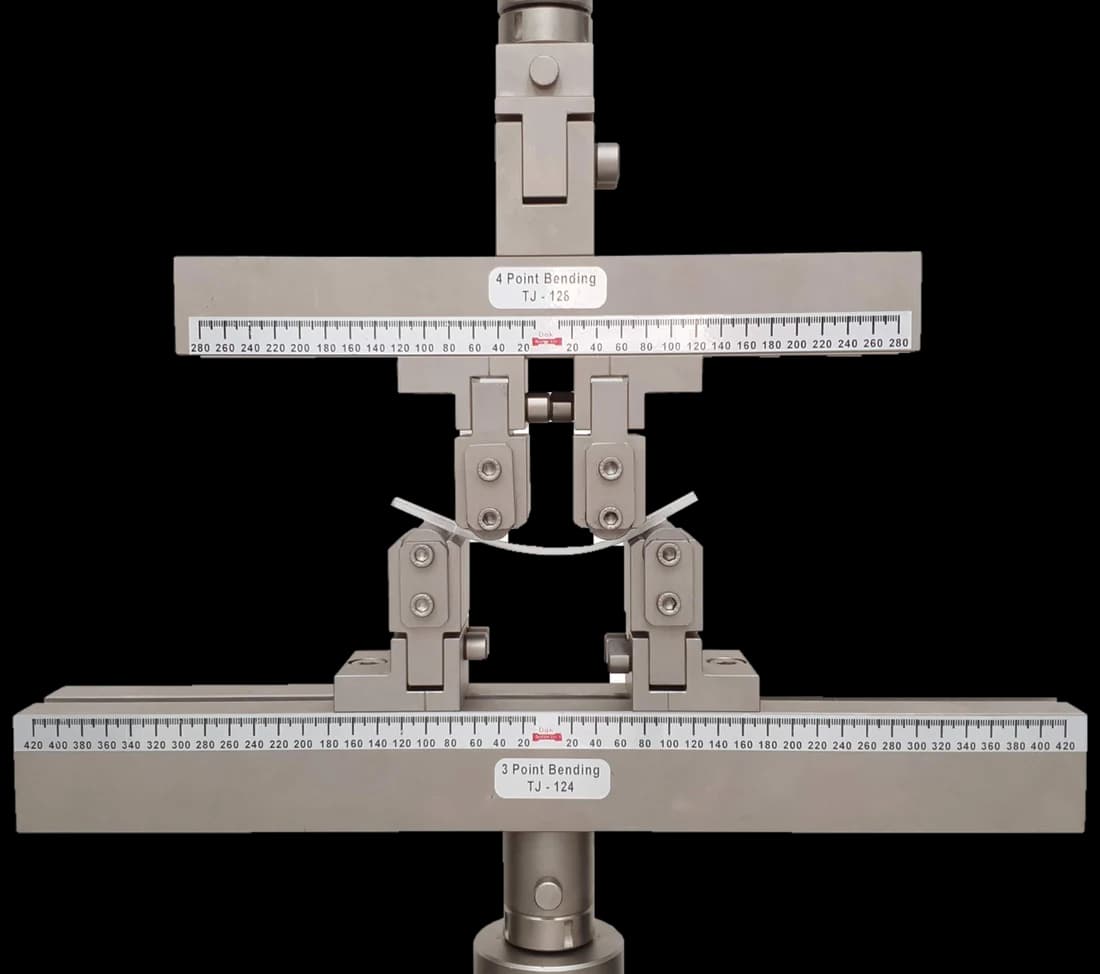
Uniform momentTJ-165
Four Point Bend Fixture
Four-point loading with adjustable inner and outer spans, so the inner rollers can be set to span at least two screw holes as the method requires.
Specifications
Testing standard
Standard Specification and Test Method for Metallic Bone Plates
Written and technically reviewed by Dak System Inc. engineeringLast reviewed
ASTM F382 tests metallic bone plates in four-point bending. Two inner rollers load the plate so at least two screw holes lie in a region of constant bending moment and zero shear. Annex A1 bends once and records load against deflection; Annex A2 repeats it as a sinusoid until the plate cracks or reaches run-out.
From the test method to your testing system
Explore the DAK machines already listed for ASTM F382, then review the grips, measurement and setup requirements below.
 Fatigue Testing MachineFatigue TesterExplore the machine →
01Understand the method
A finished bone plate is laid across four cylindrical rollers: two outer rollers support it, two inner rollers load it near mid-span. The inner pair sits so at least two screw holes lie between them, placing the holes in a region of constant bending moment and zero shear. The crosshead drives the inner rollers down and the plate bends. Annex A1 does this once, in displacement control, recording load against deflection; Annex A2 repeats it as a sinusoid at a load ratio of 0.1 until the plate cracks or reaches run-out.
The single-cycle test yields bending stiffness, bending structural stiffness and bending strength. The two stiffness figures answer different questions — how the section resists bending, and how the plate as a whole deflects in the fixture it was tested in — so neither is usable without the roller spans alongside it. Stiffness governs how load is shared between plate and healing bone: too stiff and the bone is shielded from the stimulus it needs, too compliant and the fracture gap moves. Bending strength sets the margin against a single overload, such as a fall during rehabilitation. The fatigue annex reports cycles to failure at a given load, and testing at descending loads brackets a run-out level; that figure decides whether a plate survives the months to union under repeated gait loading. F382 sets no fatigue strength a plate must achieve, and cautions that four-point bending is not the in situ loading configuration, so the numbers rank designs rather than predicting clinical life.
02Prepare the specimen and test settings
03Build the test setup on a DAK machine
The requirement splits. Annex A1 runs on an ordinary static frame in displacement control, with the rate left to the user; laboratories commonly work at around 5 mm/min. Annex A2 needs a dynamic frame able to hold a load-controlled sinusoid for a million cycles — 5 Hz and a 1,000,000-cycle run-out are the standard's suggested figures rather than absolute mandates, and R = 0.1 is near-universal practice.
No capacity is prescribed. Small-fragment plates run out at a couple of hundred newtons while heavy femoral plates go well past a kilonewton; one published study performed to F382 identified a run-out load of 1,200 N. A dynamic frame of 5 to 10 kN covers the range with headroom. The reported quantity, though, is bending moment, which follows from applied load and roller spacing together — two laboratories quoting the same newtons can be reporting quite different moments, so fixture geometry must be recorded alongside the load.
No extensometer is used; deflection is taken from the crosshead or a deflectometer. Rollers are cylindrical and commonly 6 to 12 mm in diameter — a figure that reflects fixture practice rather than a dimension the standard fixes. Which force-verification practice F382-24 names could not be confirmed from public sources, so no accuracy class is quoted here.
Four-point loading with adjustable inner and outer spans, so the inner rollers can be set to span at least two screw holes as the method requires.
SpecificationsA fatigue frame is judged on whether it holds amplitude at frequency, not on peak load, so the figures that matter here are the cycling ones.
| The method asks for | Dak supplies | |
|---|---|---|
| Load & frequency | No capacity is prescribed. Bone plates run out anywhere from a couple of hundred newtons for small-fragment plates to well over a kilonewton for heavy femoral plates — one published study working to F382 identified a run-out load of 1,200 N. A 5–10 kN dynamic frame covers the range comfortably. The useful output is the bending moment, which follows from the applied load and the roller spacing rather than from the load figure alone, so two laboratories quoting the same newtons can be reporting different moments. | Load up to 500 kN at up to 100 Hz, 60 mm actuator stroke with travel resolution up to 0.1 µm |
| Load accuracy | unknown | ±0.5% of reading |
| Gripping | Four-point bend rig with two inner loading rollers and two outer support rollers | Grips built to the specimen, with alignment held through the cycle |
| Environment | Ambient laboratory conditions; the standard defines no conditioning atmosphere or test temperature | 3009 series chambers, −150 °C to +400 °C — temperature only |
04Run the test
05Calculate, report and interpret
From the slope of the load–displacement curve and the roller geometry
A structural property of the plate as a whole, not a material modulus — the holes and the contour are included, which is the point.
The bending moment at the proof or ultimate condition
Reported as a moment rather than a stress, because a plate with holes has no single meaningful section.
The highest bending moment reaching run-out without cracking
Contoured plates are the usual nuisance. A curved or tubular plate wants to roll or creep on the support rollers, quietly changing the span and therefore the moment, and the result still looks reasonable on the plot. Roller contact marking is the next trap: a worn or undersized roller indents the plate and starts a crack at the contact line rather than at a screw hole — a fixture artefact, not a device property.
In fatigue the costliest failure is the false run-out. As the plate accumulates damage its compliance rises, and if the machine is not holding amplitude cleanly in load control the specimen sees less load than the report says. Check the recorded amplitude at the end of a run-out, not only at the start. Alignment errors that put the plate out of plane add a torsional component, and the crack then initiates on one side of a hole rather than symmetrically — a visible clue worth acting on.
06Compare methods and find answers
| Four-point (F382) | Three-point | |
|---|---|---|
| Between the inner loads | Constant moment, zero shear | Moment peaks under one nose |
| Where failure occurs | At the weakest hole in that region | Under the loading nose |
| Represents | A plate bridging a fracture gap | A point load on the plate |
| Screw holes | Loaded as they fail clinically | Only if one lies under the nose |
The geometry is chosen so the screw holes are loaded the way they actually fail. A three-point arrangement would concentrate stress under the nose and might miss the hole entirely, testing the plate section instead of the feature that governs its life.
It is the ASTM standard for the flexural properties of metallic bone plates. A finished plate is bent in four-point loading, with Annex A1 covering a single static bend and Annex A2 covering fatigue cycling at a load ratio of 0.1 until the plate cracks or reaches run-out.
Because that region carries constant bending moment and zero shear, so the holes are loaded uniformly and the weakest one governs. Screw holes are stress concentrations and they are where plates crack clinically — putting them anywhere else in the test would measure the plate section rather than the feature that decides its life.
Three-point loading peaks the moment under a single nose, so failure occurs there whether or not a hole is present. Four-point spreads a constant moment across a length, letting the plate fail at its genuinely weakest section within that length — which for a bone plate is a hole.
Because a plate with holes and a contoured profile has no single meaningful cross-section to divide by. A moment is a structural property of the plate as tested, which is what a surgeon or designer actually needs — how much bending this plate withstands, not what stress an idealised section reached.
Because plates are not uniform along their length — hole spacing, contour and thickness vary. A result therefore belongs to the part of the plate that lay in the constant-moment region, and without that record two laboratories testing the same plate can legitimately disagree.
For predicting how the plate shares load with the bone it is fixed to. A very stiff plate carries most of the load itself and shields the bone from stress, which can delay healing; too flexible and the fracture site moves more than it should. The equivalent bending stiffness from F382 is the number that lets a designer place a plate sensibly between those two failures.
Only in part, and it is not intended to. It is a bench comparison of plate designs under a defined, repeatable four-point bend, with no bone, no screws loading the holes and no cyclic loading. Its value is that two plates tested this way can be compared honestly. Fatigue behaviour, which is what usually limits a plate in service, is covered by the cyclic annex rather than the static test.
Discuss your specimen, test requirements and reporting needs with DAK engineering.
This page describes the method as practised. The governing text is the current edition from the issuing body. Tell us what you are testing and we will answer with the machine, the fixture and a quotation.