

Testing standard
ISO 14801 Dynamic Fatigue Testing of Dental Implants
Dentistry — Implants — Dynamic loading test for endosseous dental implants
Written and technically reviewed by Dak System Inc. engineeringLast reviewed
ISO 14801 is the fatigue test for dental implants. The implant is clamped at 30° to the machine axis with the clamping plane 3 mm below nominal bone level — standing in for bone loss — and a load is cycled onto a cap 11 mm above that plane. The tilt and the lever turn axial force into bending, and cycling continues to fracture or run-out.
At a glance
- Test type
- Fatigue — a load is applied over and over until something fails
- Published by
- ISO
- Edition
- ISO 14801:2016
- Runs on
- Fatigue Tester
From the test method to your testing system
Explore DAK equipment for ISO 14801, then review the specimen and setup requirements below.
 Fatigue Testing MachineFatigue TesterExplore the machine →
Jump to a specific section
01Understand the method
What the test does
An implant is clamped in a holder inclined 30 degrees to the machine axis, with the clamping plane 3 mm below the point representing bone level, leaving a defined length unsupported as bone loss would. The abutment and screw are fitted, and a hemispherical cap sits 11 mm from the clamping plane. A flat platen, free to slide sideways, presses on that cap and cycles sinusoidally between a chosen peak load and a tenth of it. The tilt and the lever turn axial force into bending, and cycling continues until the specimen fractures or reaches run-out.
What it measures, and why it matters
Each specimen gives a pair of numbers — peak load applied and cycles survived — and a set run at descending loads builds the load-cycle diagram from which a fatigue limit is read. What is really being applied is a bending moment: in the standard geometry it is 5.5 times the force at the cap, so a few hundred newtons becomes a substantial moment at the implant neck. That is where the method earns its keep, since chewing loads arrive off-axis and the neck and the abutment screw joint are where implants fail. It is not a measure of the base material's fatigue properties, and does not predict clinical survival.
02Prepare the specimen and test settings
Geometry is the method
Almost every number in this standard is a dimension. Change any of them and the bending moment changes, so results stop comparing.
- Tilt
- 30° to the machine axis
- Clamping plane
- 3 mm below the nominal bone levelRepresenting bone loss, and leaving that length of implant unsupported. It is the single most severe assumption in the method.
- Load point
- 11 mm above the clamping planeThe lever arm. Together with the tilt it fixes the bending moment for a given force.
- Hemispherical cap
- On the abutment
- Platen
- Flat and free to slide sidewaysSo it applies force without applying a transverse constraint the model does not intend.
- Assembly
- Abutment and screw fitted as clinically intendedIncluding the screw torque, which is part of the specimen.
This is a worst-case comparative model, not a prediction of clinical life. It assumes 3 mm of bone loss, a 30° off-axis load and no biological support — conditions chosen to discriminate between designs rather than to represent an average patient.
Cycling
- Waveform
- Sinusoidal
- Load ratio
- Peak to one tenth of peakR = 0.1 — always compressive, never reversing into tension.
- Run-out
- Declared in advanceCommonly five million cycles for dental implants.
- Frequency
- Chosen so heating and inertia stay negligibleAnd reported, because a higher frequency shortens the test but can change the answer.
- Medium
- Air or a specified fluidReport which. Testing wet is more severe for some material systems.
03Build the test setup on a DAK machine
What the machine must be capable of
Peak loads sit in the low hundreds of newtons, so capacity is not the constraint: a few hundred newtons will do the work, and one to two kilonewtons of dynamic capability leaves headroom. Accuracy is specified instead — force error must stay within 5 % at maximum load, verified to ISO 7500-1.
Loading is sinusoidal at a load ratio of 0.1, so the trough never reaches zero and the joint is never unloaded. Frequency is capped at 15 Hz in air and 2 Hz in liquid, the lower cap acknowledging that a bath cannot follow a fast cycle. Run-out is generally taken as five million cycles in air and two million in liquid — roughly four and twelve days at those caps. Both are in universal use but sit beyond the freely published part of the standard, so confirm them against the purchased text. Unattended running of that length makes automatic failure detection a requirement, not a convenience.
No extensometer is used. The fixture carries the method: the inclination, the clamping offset and the lever length are all held to tight tolerances, and the platen must stay free to move transversely — one that grips the hemisphere adds a side constraint and quietly changes the moment. Where corrosion fatigue is expected or polymeric parts are present, the specimen is immersed in saline or another physiological medium at 37 °C ± 2 °C; otherwise air at 20 °C ± 10 °C serves. The choice must be justified and reported.
The machine this method needs
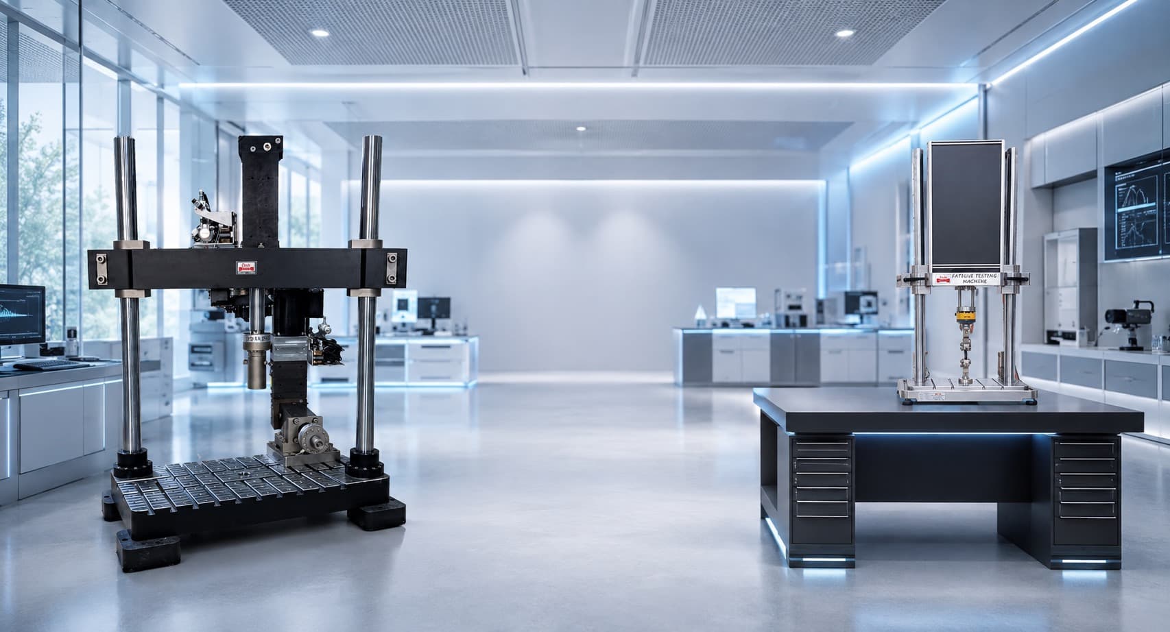
Running ISO 14801 on the Fatigue Tester
A fatigue frame is judged on whether it holds amplitude at frequency, not on peak load, so the figures that matter here are the cycling ones.
| The method asks for | Dak supplies | |
|---|---|---|
| Load & frequency | The standard sets an accuracy demand, not a capacity: force error must not exceed ±5 % at maximum load per ISO 7500-1. Peak loads sit in the low hundreds of newtons, so machines from about 500 N upwards handle the work and 1–2 kN of dynamic capacity gives comfortable headroom. The bending moment matters more than the raw force — with the standard 11 mm lever at 30 degrees, moment in N·mm is 5.5 times the applied force in newtons. | Load up to 500 kN at up to 100 Hz, 60 mm actuator stroke with travel resolution up to 0.1 µm |
| Load accuracy | ISO 7500-1 (±5 % at maximum load) | ±0.5% of reading |
| Gripping | Angled specimen holder with rigid clamp or embedding pot (embedding modulus above 3 GPa), hemispherical loading cap and transversely free flat platen | Grips built to the specimen, with alignment held through the cycle |
| Environment | Air at 20 °C ± 10 °C, or normal saline / physiologic medium at 37 °C ± 2 °C where corrosion fatigue or polymeric components are involved; the environment chosen must be justified and reported | 3009 series chambers, −150 °C to +400 °C — temperature only |
04Run the test
How the test runs
- Assemble the implant, abutment and screw as clinically intended, at the specified torque.
- Clamp the implant at 30°, with the clamping plane 3 mm below nominal bone level.
- Verify the load point sits 11 mm above the clamping plane.
- Fit the hemispherical cap and bring the sliding flat platen into contact.
- Declare the run-out count and the failure criterion.
- Cycle sinusoidally between the peak load and a tenth of it.
- Continue to fracture or to run-out.
- Record where the failure occurred — implant body, abutment, or screw.
- Repeat at several load levels to establish the fatigue limit.
See the machine
05Calculate, report and interpret
What comes out
M = F × l × sin(30°)
- F
- applied force, N
- l
- distance from clamping plane to load point, 11 mm
Which is why every dimension in the setup is specified. The force alone means nothing without the geometry that turns it into a moment.
The highest load at which specimens reach run-out without fracture
Established by testing at several levels. It is the headline figure for a dental implant system and the one regulators compare against a predicate.
What the report has to contain
- Reference to ISO 14801
- Implant system, sizes, materials and abutment configuration
- Screw tightening torque
- Clamping geometry actually achieved — tilt, clamping plane, lever arm
- Load ratio and frequency
- Test medium — air or fluid
- Declared run-out count
- Loads applied and cycles endured, with run-outs identified
- FAILURE LOCATION for every specimen
- Number of specimens per load level
What goes wrong in practice
Movement in the embedding spoils otherwise quiet data. If the implant settles in the pot, or the clamp relaxes, the free length grows and the moment arm with it, so the specimen sees more than the load recorded — visible only as a curve that drifts across a batch.
Abutment screw loosening is the second. Preload lost during cycling lets the joint micro-move, and the result is often reported as an implant fracture when it is really a joint failure; retightening between runs to keep a test going destroys comparability.
The third is thermal, and belongs to fast dry testing: near the upper frequency cap, polymeric components and the embedding medium warm, and the specimen that fails is no longer the one that was fitted.
06Compare methods and find answers
What this model does and does not represent
| ISO 14801 model | Clinical reality | |
|---|---|---|
| Bone support | None for 3 mm below the platform | Usually intact at placement |
| Load direction | Fixed at 30° | Varies with occlusion |
| Load | Constant amplitude | Highly variable |
| Environment | Air or a specified fluid | Biological, loaded intermittently |
Every simplification here makes the test more severe and more repeatable, which is what a comparative bench standard is for. It supports a regulatory comparison against a predicate device; it does not forecast how long an implant will last in a particular patient.
Questions we are asked about this test
What is ISO 14801?
It is the international standard for dynamic fatigue testing of endosseous dental implants. The implant is clamped at 30° to the loading axis with 3 mm of its length unsupported, and a load is cycled onto a cap 11 mm above the clamping plane until the specimen fractures or reaches run-out.
Why is the implant tilted 30 degrees?
To turn the machine's axial force into a bending moment. A dental implant in service is rarely loaded straight down its axis; occlusal forces arrive off-centre and bending is what actually breaks implants and abutment screws. The tilt, combined with the 11 mm lever, produces that bending in a repeatable way.
Why is the clamping plane 3 mm below bone level?
It represents bone loss. Leaving 3 mm of the implant unsupported lengthens the effective lever and puts the highest stress at the implant platform, where fractures actually occur. It is a deliberately severe assumption — most implants at placement have full bone support — chosen so the test discriminates between designs.
Does ISO 14801 predict how long an implant will last?
No. It is a comparative bench model with fixed geometry, constant-amplitude loading and no biology. Its purpose is to let one implant system be compared with another, typically against a predicate device for regulatory submission. Clinical life depends on bone quality, occlusion, hygiene and surgical placement, none of which the model contains.
Why must the platen be free to slide?
So it applies force to the cap without applying a transverse constraint. A fixed platen would resist the sideways movement the tilted implant makes as it deflects, adding a restraint the model does not intend and changing the moment at the implant platform.
Why does failure location matter?
Because it points at what to change. An implant body fracture, an abutment fracture and a screw fracture all end the test at the same cycle count but implicate different parts of the system. Recording only the number discards the half of the result a designer can act on.
Related
Industries that test to it
Other standards explained
Planning ISO 14801 testing?
Discuss your specimen, test requirements and reporting needs with DAK engineering.
This page describes the method as practised. The governing text is the current edition from the issuing body. Tell us what you are testing and we will answer with the machine, the fixture and a quotation.