

Testing standard
ASTM F1798 Static and Fatigue Testing of Spinal Implant Interconnections
Standard Test Method for Evaluating the Static and Fatigue Properties of Interconnection Mechanisms and Subassemblies Used in Spinal Arthrodesis Implants
Written and technically reviewed by Dak System Inc. engineeringLast reviewed
ASTM F1798 characterises a single spinal implant interconnection — a pedicle screw, a hook, a cross-connector joined to a rod. Everything except the joint is made rigid so the load path runs through the connection alone, and it is loaded in one of six directions: three forces and three moments, each as a slow ramp to failure and as a cycled sinusoid.
At a glance
- Test type
- Fatigue — a load is applied over and over until something fails
- Published by
- ASTM
- Edition
- F1798-24
- Runs on
- Fatigue Tester
From the test method to your testing system
Explore DAK equipment for ASTM F1798, then review the specimen and setup requirements below.
 Fatigue Testing MachineFatigue TesterExplore the machine →
Jump to a specific section
01Understand the method
What the test does
A single interconnection is isolated and loaded until it fails or lets go. The rod and its mating component — a pedicle screw, a hook, a cross-connector — sit in a jig built so everything except the joint is rigid, and the load path runs through the connection alone. Load is applied in one of six directions: three forces along the implant axes, three moments about them. Each direction has two variants: a slow ramp to failure, and a sinusoid cycled until the joint fails functionally or reaches a run-out of 2,500,000 cycles.
What it measures, and why it matters
The static tests give the force or moment the joint carries before it yields, slips or comes apart, and the displacement or rotation at which it does. Gripping capacity, the axial case along the rod, matters most directly: lose it and the correction set in theatre goes with it, though nothing has broken. The moment cases matter because a spinal construct sees flexion, extension and torsion far more than pure tension. The fatigue variants report cycles to functional failure — the practical question of whether a connection stays tight for the months before fusion. Because the test medium is a reported variable, a joint characterised dry is not describing the same behaviour as one run under saline.
02Prepare the specimen and test settings
The joint in isolation
- What is tested
- One interconnectionNot the construct. The jig makes everything else rigid so nothing else can be the weak link.
- Six directions
- Three forces along the axes, three moments about themA joint that is strong in one direction can be weak in another, which a single-direction test would never reveal.
- Two variants per direction
- A ramp to failure, and a cycled sinusoid
- Run-out
- 2 500 000 cycles
- Functional failure
- Defined before the testA joint can loosen and slip without anything breaking, and that counts as failure — which makes the criterion a decision rather than an observation.
- Record assembly torque
- Every specimenDakIt is the single variable most likely to explain scatter in an interconnection test.
Static and dynamic
- Static
- Slow ramp to failure
- Dynamic
- Sinusoid to functional failure or run-out
- Run-out count
- 2 500 000 cycles
- Frequency
- Chosen so heating and inertia stay negligible
03Build the test setup on a DAK machine
What the machine must be capable of
Five of the six directions run on a single-axis dynamic frame with the right jig, but the axial torque case is a rotary moment and needs a torsion axis or a biaxial machine.
Nothing in the method fixes a frame rating. Forces are modest and the resolution demands are not: a screw-to-rod joint typically holds from a few hundred newtons to around two kilonewtons, and the moment cases a handful of newton-metres. A dynamic frame of 5 kN or less with a torque axis of roughly 20 to 50 N·m reaches all six directions. The harder requirement is holding a clean, repeatable small-amplitude cycle for two and a half million cycles without drift; an oversized load cell working at the bottom of its range is the usual reason a result cannot be trusted.
Static rates quoted by testing laboratories are of the order of 20 N/s, or about 25 mm/min, for the force cases and about 25 N·m/min, or roughly 25 degrees/min, for the moment cases; fatigue is commonly run at 5 Hz. Those figures reflect laboratory practice rather than rates the method fixes. No public account names the force-verification practice it invokes, so the current edition governs on both counts.
No extensometer is involved; fixture geometry replaces it. Each moment case is defined by a lever arm set by the jig, so a few millimetres of error there scales every reported moment, and the jig must be stiff enough that measured displacement belongs to the joint rather than the rig.
The machine this method needs
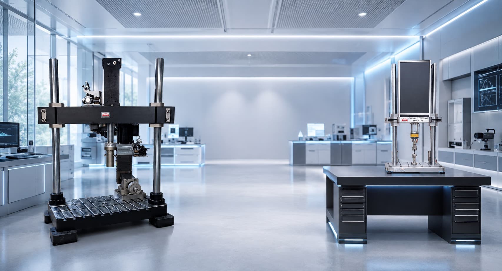
Running ASTM F1798 on the Fatigue Tester
A fatigue frame is judged on whether it holds amplitude at frequency, not on peak load, so the figures that matter here are the cycling ones.
| The method asks for | Dak supplies | |
|---|---|---|
| Load & frequency | No capacity is prescribed. Interconnection work is modest in force but demanding in resolution: the axial gripping capacity of a pedicle screw-to-rod joint typically runs from a few hundred newtons to around two kilonewtons, while the moment cases run to a handful of newton-metres. A dynamic frame of 5 kN or less, paired with a torque axis of roughly 20–50 N·m, covers all six loading directions — the harder requirement is holding a clean, repeatable small-amplitude cycle for 2.5 million cycles. | Load up to 500 kN at up to 100 Hz, 60 mm actuator stroke with travel resolution up to 0.1 µm |
| Load accuracy | unknown | ±0.5% of reading |
| Gripping | Direction-specific jigs isolating a single interconnection — screw-to-rod, hook-to-rod or cross-connector | Grips built to the specimen, with alignment held through the cycle |
| Environment | The medium is a reported test variable — dry, saline drip, saline immersion or simulated body fluid — because it changes the fretting, corrosive and lubricating behaviour at the joint | 3009 series chambers, −150 °C to +400 °C — temperature only |
04Run the test
How the test runs
- Assemble the interconnection to the manufacturer's specified torque and record it.
- Mount it in the jig so that everything except the joint is rigid.
- Confirm the load path runs through the connection alone.
- Choose the direction — one of three forces or three moments — and record it.
- Define functional failure before starting.
- For the static variant, ramp slowly to failure and record the peak.
- For the dynamic variant, cycle sinusoidally to functional failure or to 2 500 000 cycles.
- Record whether the joint broke, slipped or loosened.
- Repeat across the directions the specification requires.
See the machine
05Calculate, report and interpret
What comes out
Peak force or moment at failure, in the loaded direction
Reported per direction. Six directions give six numbers and the set is the result rather than any one of them.
The highest load or moment reaching 2 500 000 cycles without functional failure
What the report has to contain
- Reference to ASTM F1798
- Component identification, sizes and materials
- ASSEMBLY TORQUE applied
- Which of the six directions was loaded
- The definition of functional failure used
- Static strength in that direction
- Fatigue run-out level, with run-outs identified as such
- Whether failure was fracture, slip or loosening
- Number of specimens per direction
What goes wrong in practice
The most common dispute is over what counts as failure. Interconnections rarely snap; they loosen, and the joint keeps cycling while quietly giving up displacement. Unless a loosening criterion is defined before the run and monitored during it, two laboratories can report very different lives from identical hardware.
Set-screw stripping is next. Over-torquing on assembly, or reusing a locking element already seated once, damages the thread form and shifts the result onto the fastener rather than the connection under test. Amplitude loss follows from it. A joint that has begun to let go absorbs part of every stroke in free movement before it carries anything, so the peak the controller reports is not the peak the interconnection sees, and a run-out logged at 2,500,000 cycles was never earned.
Fretting is the slow one. Under saline the rod and the clamp interface accumulate debris and a dark stain long before any measurable slip, so photographing the interface at intervals is worth more than the load trace.
06Compare methods and find answers
F1798 and F1717
| ASTM F1798 | ASTM F1717 | |
|---|---|---|
| Scope | One interconnection | The whole construct |
| Everything else | Made rigid | Real, and able to fail |
| Directions | Six, separately | Four defined loading methods |
| Answers | How strong is this joint? | How does the system perform? |
A construct test finds the weakest element; an interconnection test characterises one joint properly. Passing F1717 does not mean every connection in the system is strong — only that none of them was the first to fail in that particular model.
Questions we are asked about this test
What is ASTM F1798?
It is the ASTM standard for evaluating the static and fatigue properties of interconnection mechanisms in spinal implants. A single joint — a screw, hook or cross-connector on a rod — is isolated in a rigid jig and loaded in one of six directions, both as a slow ramp to failure and as a cycled sinusoid.
Why six loading directions?
Because a joint can be strong in one and weak in another. A set screw arrangement might resist axial pull-out well and rotate under a moment about the rod axis, and a single-direction test would never show it. Three forces and three moments cover the ways a real construct loads a connection, and the set of six is the result rather than any one figure.
What is functional failure?
Loss of the joint's function, which is not the same as fracture. A connection can loosen and slip along the rod without anything breaking, and the construct is no longer doing its job — so that counts as failure. Because it is a judgement rather than an event, the definition has to be set before the test rather than after.
Why is everything except the joint made rigid?
So the joint is the only thing that can fail. In a real construct the weakest element decides the result, which is what F1717 is for. Here the question is how strong this particular connection is, so the jig removes every other candidate — otherwise the test would keep measuring whatever else happened to be marginal.
Why does assembly torque have to be recorded?
Because it is the variable most likely to explain scatter between nominally identical specimens. A set screw at the low end of its torque tolerance behaves differently from one at the high end, and without the record there is no way to tell an assembly problem from a design one.
Why test a single interconnection rather than the whole construct?
Because a construct failure rarely tells you which joint gave way first, and because interconnections are the parts most likely to loosen. Isolating one joint — with everything else made rigid — turns a diffuse result into a specific one, and lets a manufacturer compare two locking mechanisms without the rest of the system masking the difference.
What is the relationship between F1798 and F1717?
They are complementary and normally run together. F1798 characterises a single interconnection in isolation, in six loading directions, and answers whether the joint holds. F1717 loads an assembled construct in a vertebrectomy model and answers whether the system holds. A construct can fail F1717 because of a component F1798 would have flagged, which is why the component test usually comes first.
Related
Industries that test to it
Other standards explained
Planning ASTM F1798 testing?
Discuss your specimen, test requirements and reporting needs with DAK engineering.
This page describes the method as practised. The governing text is the current edition from the issuing body. Tell us what you are testing and we will answer with the machine, the fixture and a quotation.