Testing standard

ASTM F1264

Standard Specification and Test Methods for Intramedullary Fixation Devices

Written and technically reviewed by Dak System Inc. engineeringLast reviewed

ASTM F1264 combines a specification with four test methods for intramedullary fixation devices: static four-point bend, static torsion, bending fatigue, and bending fatigue of locking screws. It states explicitly that it does not define levels of performance or predict clinical outcome.

At a glance

Test type
Fatiguea load is applied over and over until something fails
Published by
ASTM
Edition
F1264-24

What the test does

Four methods sit in annexes to the specification. Annex A1 is a static four-point bend, giving bending strength and stiffness from the load-displacement curve using the fixture's outer and inner spans. Annex A2 is a static torsion test, recording torque against angle of twist over a stated gauge length. Annex A3 cycles the device in bending at a chosen load to a defined run-out. Annex A4 repeats that fatigue arrangement on the locking screws. Each annex is reported separately, with its own geometry and parameters.

What it measures, and why it matters

How an intramedullary nail behaves in the two modes that matter clinically, statically and then over time. Bending is the obvious one. Torsion is the one more easily overlooked, and it is a primary function: a nail that resists bending well but twists easily lets the fracture fragments rotate against one another, which is a failure of fixation with nothing broken. The locking screws earn their own annex because they are the smallest section in the construct and frequently the first thing to break, so a nail can pass its own fatigue test while its screws fail in service.

Four methods, four annexes

Bending and torsion, each statically and then in fatigue, plus the locking screws that are usually the weakest part.

Annex A1
Static four-point bendFour-point gives a constant moment between the inner rollers, so the result does not depend on exactly where along the nail the load landed.
Annex A2
Static torsionRotational control is a primary clinical function of a nail, so torsional stiffness and strength matter as much as bending.
Annex A3
Bending fatigue
Annex A4
Bending fatigue of locking screwsA separate annex because the screws often fail before the nail does.
Also specifies
Design characterisation, labelling and material requirements
Explicitly not intended
To define performance levels or predict clinical performanceThe standard says clinical outcome prediction requires knowledge that is not yet available.

An unusually honest scope. The standard states that it identifies needs for further development of test methods and performance criteria — that is, it says openly where the science is not yet settled.

Test speed

Static
A controlled rate to the defined endpoint
Fatigue
A defined frequency and run-out
Reported
Bending and torsional strength and stiffness; fatigue survival or cycles
Test the locking screws too
Not only the nailDakThe screws are the smallest section in the construct and frequently the first thing to break.

Calculations

Bending stiffness

From the load-displacement curve in four-point bending, using the fixture spans

spans
the outer and inner roller separations

Both spans are needed to interpret the result, so both belong in the report.

Torsional stiffness

Torque per unit angle of twist over the gauge length

The gauge length must be stated — a longer nail twists further for the same torque and the same material.

Fatigue result

Survival at a stated load to a stated run-out, or the cycle at failure

Load and run-out together, as for every fatigue figure.

How the test runs

  1. 01Identify the device, its diameter, length and locking configuration.
  2. 02Confirm the material and labelling requirements are met.
  3. 03For Annex A1, set the four-point bend fixture spans and record both.
  4. 04Load statically to the defined endpoint and determine bending strength and stiffness.
  5. 05For Annex A2, grip the nail at both ends and apply torsion, recording torque against angle.
  6. 06For Annex A3, verify the applied force dynamically at the test frequency.
  7. 07Cycle in bending at the chosen load to the defined run-out.
  8. 08For Annex A4, repeat the fatigue arrangement on the locking screws.
  9. 09Record survival or the cycle at failure for each fatigue test.
  10. 10Photograph and, where useful, section failed devices.
  11. 11Report each annex separately, with its own geometry and parameters.

Grips and fixtures for this method

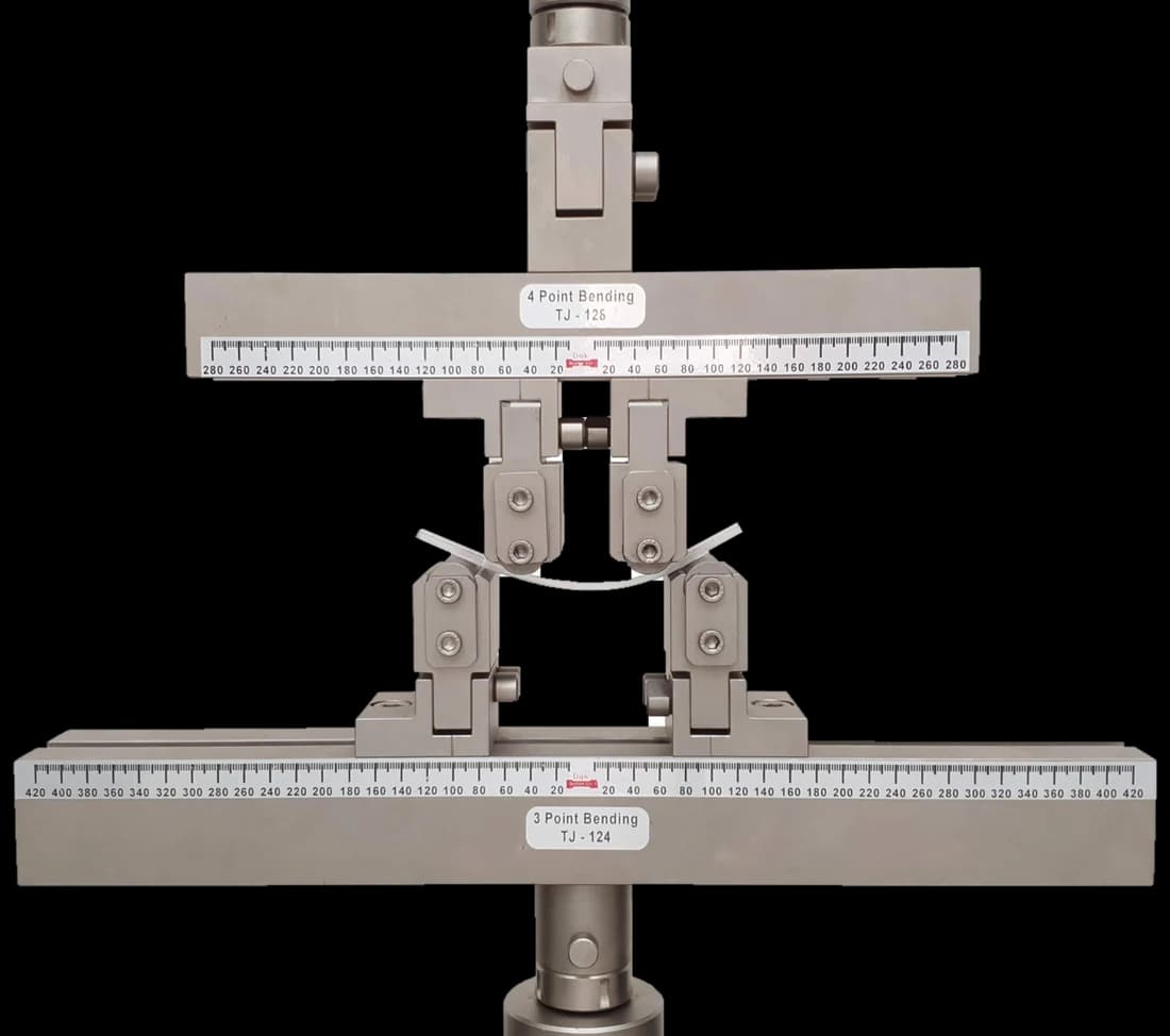
Four point bending fixture with two inner and two outer supports
Uniform momentTJ-165

Four Point Bend Fixture

A four-point bend fixture gives a constant bending moment between the inner rollers, which is what lets a nail be assessed without the result depending on exactly where along it the load happened to land.

Specifications
Self-identifying

Load Cells

A load cell matched to the device rather than the frame — a small-diameter nail and a femoral nail differ by an order of magnitude.

Specifications

What the report has to contain

  • Reference to ASTM F1264, the edition and which annexes were used
  • Device identification, diameter, length, material and locking configuration
  • Four-point bend spans, both outer and inner
  • Torsion gauge length
  • Static rates, or fatigue frequency and waveform
  • Bending strength and stiffness
  • Torsional strength and stiffness
  • Fatigue load, run-out and outcome for the nail and for the locking screws separately
  • How dynamic force was verified
  • Failure locations, with photographs

What the machine must be capable of

A wide range of force, since a small-diameter nail and a femoral nail differ by an order of magnitude, which argues for a load cell chosen per device rather than per frame. A four-point bend fixture with settable spans, a torsion capability for Annex A2, and cyclic loading for the two fatigue annexes with the applied force verified dynamically at the test frequency — a statically calibrated frame that under-delivers in motion passes that error into every cycle of a long run.

What goes wrong in practice

Reporting a stiffness without the fixture spans, or a torsional stiffness without the gauge length, either of which makes the figure unreproducible. Testing the nail and not the locking screws. Quoting a fatigue result without both the load and the run-out. Verifying force statically for a dynamic test. And presenting results as evidence of clinical performance, which the standard explicitly declines to support on the grounds that the necessary knowledge does not yet exist — a rare piece of candour, and one worth quoting back when a submission overreaches.

ASTM F1264 or ISO 7206-4

ASTM F1264ISO 7206-4
DeviceIntramedullary nails and rodsStemmed femoral components
LoadingBend and torsion, static and fatigueCyclic, at specified angles
Performance criteriaExplicitly not definedSpecified in the standard
Both requireDynamic force verificationDynamic force verification

A useful contrast in philosophy. The ISO hip standard fixes the forces and cycles a device must survive; this ASTM standard supplies methods and says openly that the criteria are not yet settled.

Questions we are asked about this test

What is ASTM F1264?

It is the ASTM document for intramedullary fixation devices — the nails and rods placed inside the medullary canal to fix long bone fractures. It combines a specification covering design characterisation, materials and labelling with four test methods in annexes: static four-point bend, static torsion, bending fatigue, and bending fatigue of locking screws. The current designation is ASTM F1264-24.

Why four-point bending rather than three-point?

Because four-point loading produces a constant bending moment between the two inner rollers, whereas three-point produces a peak directly under a single load point. On a long nail that distinction matters: with four-point the result does not depend on exactly where along the device the load happened to land, and any weak section within the constant-moment region will find itself equally loaded.

Why is torsion tested separately?

Because rotational control is one of the primary clinical functions of an intramedullary nail. A nail that resists bending well but twists easily allows the fracture fragments to rotate relative to one another, which is a failure of fixation even with nothing broken. Torsional stiffness and strength are therefore measured in their own right rather than inferred from the bending behaviour.

Why do the locking screws get their own annex?

Because they are frequently the first thing to fail. The screws are the smallest section in the whole construct and they carry load between the nail and the bone, so a device can pass its own bending fatigue test comfortably while its locking screws break in service. Testing them separately is what stops that being discovered clinically.

Does this standard say what a good device looks like?

No, and it says so explicitly. Its stated intent is to characterise design and mechanical function and to provide test methods, not to define levels of performance or predict case-specific clinical performance — because, in its own words, clinical outcome prediction requires knowledge that is not yet available. It also states that it identifies needs for further development of test methods and performance criteria, which is an unusually candid thing for a standard to say.

Why must both bend spans be reported?

Because the geometry determines the result. Bending stiffness computed from a load-displacement curve depends on both the outer and the inner roller separations, so a stiffness quoted without them cannot be reproduced or compared. The same logic applies to the torsion gauge length: a longer nail twists further for the same torque and the same material.

How does it compare with the ISO hip standard?

They differ in philosophy, which is instructive. ISO 7206-4 specifies the endurance forces and the cycle counts a hip stem must survive, so it returns a pass or fail against a requirement in the standard. F1264 supplies methods and leaves the criteria open, on the stated grounds that the knowledge to set them does not yet exist. Both approaches are defensible; knowing which one you are working under changes how a result should be presented.


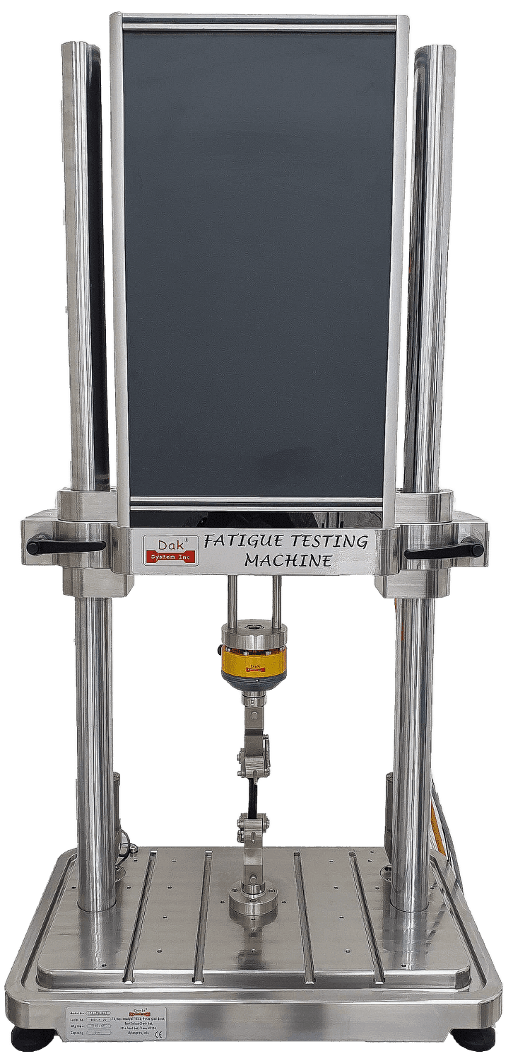
Running ASTM F1264 on the Fatigue Tester

A fatigue frame is judged on whether it holds amplitude at frequency, not on peak load, so the figures that matter here are the cycling ones.

The method asks forDak supplies
Load & frequencyWide — a small-diameter nail and a femoral nail differ by an order of magnitudeLoad upto 500 kN at upto 100 Hz, 60 mm actuator stroke with travel resolution upto 0.1 µm
Load accuracyASTM E4, with dynamic verification for the fatigue annexes±0.5% of reading
GrippingA four-point bend fixture for the static bend, a torsion arrangement for the torsion method, and cyclic fixtures for the fatigue annexesGrips built to the specimen, with alignment held through the cycle
Environment23 ± 2 °C standard laboratory atmosphere3009 series chambers, −150 °C to +400 °C — temperature only

This page describes the method as practised. The governing text is the current edition from the issuing body. Tell us what you are testing and we will answer with the machine, the fixture and a quotation.