

Testing standard
ASTM E466 Force-Controlled Axial Fatigue Testing of Metals
Standard Practice for Conducting Force Controlled Constant Amplitude Axial Fatigue Tests of Metallic Materials
Written and technically reviewed by Dak System Inc. engineeringLast reviewed
ASTM E466 is the practice for force-controlled constant-amplitude axial fatigue tests on metals. A specimen is cycled between a fixed maximum and minimum force until it fails or reaches a preset cycle count. One test gives a single point; the value is in a set of them run at several stress levels, from which the stress-life curve is drawn.
At a glance
- Test type
- Fatigue — a load is applied over and over until something fails
- Published by
- ASTM
- Edition
- E466-21
- Material
- Metals, alloys & welds
- Runs on
- Fatigue Tester
From the test method to your testing system
Explore DAK equipment for ASTM E466, then review the specimen and setup requirements below.
 Fatigue Testing MachineFatigue TesterExplore the machine →
Jump to a specific section
01Understand the method
What the test does
A machined metal specimen with a reduced central section is held at both ends in an axially aligned load train and cycled between a fixed maximum and a fixed minimum force. Loading is periodic and usually sinusoidal, and the amplitude does not change from one cycle to the next. Cycling continues until the specimen meets the failure criterion declared beforehand, normally separation, or until a predetermined number of cycles has passed without it. Nothing is measured on the specimen meanwhile: the machine holds the amplitude and counts.
What it measures, and why it matters
A single test yields one number — cycles endured at a stated stress amplitude and mean stress — and alone it means little. Value comes from a set run at several stress levels, from which the stress-life curve is drawn. A designer reads an allowable stress off that curve at a chosen design life, or the stress below which no failure appears within the cycle count the laboratory can afford. Comparing curves is how a change in melt practice, surface finish or heat treatment is shown to matter, and notched specimens run beside plain ones show how sensitive an alloy is to stress concentration. Because strains stay predominantly elastic, the practice describes long-life behaviour only.
02Prepare the specimen and test settings
Specimen families and surface finish
Surface finish matters more here than in any static test, because a fatigue crack starts at the surface and almost nothing else about the specimen can compensate for a bad one.
- Round, tangentially blended
- Test section about twice the diameterProportions are from a superseded edition and should be checked against the current text.
- Continuous-radius (hourglass) bar
- Radius more than three times the minimum diameter
- Flat coupons
- For sheet and plate
- Gripped ends
- Considerably more area than the test sectionSo the damage accumulates where it is being measured rather than in the grips.
- Surface finish
- Controlled and reportedMachining marks transverse to the load axis are crack starters. Longitudinal polishing is normal.
- Alignment
- Verified, not assumedBending superimposed on axial load shortens life dramatically and silently.
- Declare the failure criterion first
- Before the test, not afterDakNormally separation. Deciding afterwards what counted as failure is how a fatigue programme becomes unusable.
Cycling
- Waveform
- Periodic, usually sinusoidal
- Amplitude
- Constant, cycle to cycleThis is the defining feature — the machine holds the force amplitude and counts.
- Frequency
- Chosen so heating does not affect the resultAnd reported, because it can.
- End of test
- The declared failure criterion, or a runout cycle count
- Nothing is measured meanwhile
- The machine holds and counts
Force control is the binding requirement. A frame that can pull the specimen apart statically is not necessarily able to hold a constant force amplitude for millions of cycles — that needs closed-loop control and a load train that does not loosen.
03Build the test setup on a DAK machine
What the machine must be capable of
No force capacity is prescribed; an accuracy demand is prescribed instead. The force amplitude must be held close to target at the test frequency, verified dynamically rather than by static calibration, because a load cell and control loop exact at rest can fall short at speed. Capacity follows the specimen — tens of kilonewtons at peak for a stout bar in a high-strength alloy, a few for thin sheet coupons — and the frame is chosen well above peak cyclic force, since amplitude control degrades near full scale. Alignment is the second hard requirement, verified with a strain-gauged specimen rather than assumed: the practice caps the bending strain the load train may impose.
The usual working band is about 0.01 to 100 Hz, across which fatigue strength is generally unaffected by rate for most metallic engineering materials, though localised yielding can heat the specimen and shift the result. No run-out is fixed; one million to ten million cycles is the common laboratory choice.
No extensometer is fitted. Round specimens take threaded-end or button-head axial adapters and sheet takes hydraulic wedge grips; either way the load train must transmit the cycle without backlash, since a joint that unloads and re-seats corrupts the waveform and frets the specimen where it is held. Testing is in laboratory air at room temperature, recorded and reported.
The machine this practice needs
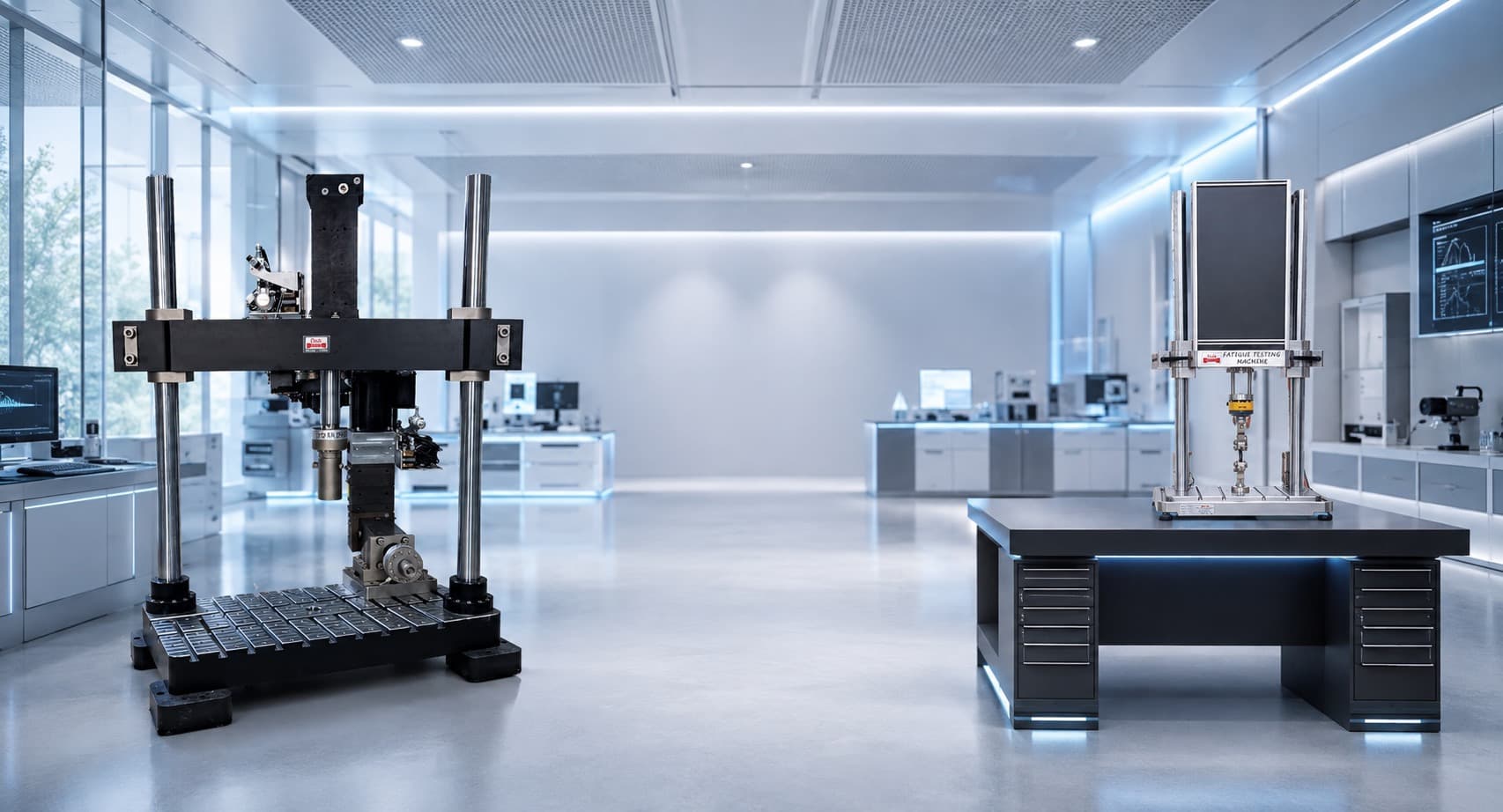
Running ASTM E466 on the Fatigue Tester
A fatigue frame is judged on whether it holds amplitude at frequency, not on peak load, so the figures that matter here are the cycling ones.
| The method asks for | Dak supplies | |
|---|---|---|
| Load & frequency | The practice prescribes no force capacity at all — it prescribes an accuracy demand. Size the machine from the specimen: a 5–25 mm diameter round bar in a high-strength alloy can need tens of kilonewtons at peak, while thin sheet coupons cycle under a few kilonewtons. What governs the choice is that the varying stress amplitude must hold within 2 % of the target value at the test frequency, verified by dynamic force verification to ASTM E467, so the frame is normally chosen well above the peak cyclic force rather than close to it. | Load up to 500 kN at up to 100 Hz, 60 mm actuator stroke with travel resolution up to 0.1 µm |
| Load accuracy | ASTM E467 | ±0.5% of reading |
| Gripping | Threaded-end or button-head axial adapters, or hydraulic wedge grips for sheet, on a precision-aligned dynamic load train | Grips built to the specimen, with alignment held through the cycle |
| Environment | Laboratory air at room temperature; temperature, relative humidity and the surrounding medium are recorded periodically through the test and reported | 3009 series chambers, −150 °C to +400 °C — temperature only |
04Run the test
How the test runs
- Machine specimens with the test section proportioned to the family in use.
- Finish the surface to the specified condition, polishing longitudinally.
- Verify alignment of the load train before loading anything.
- Declare the failure criterion and the runout cycle count in advance.
- Choose the stress amplitude and mean stress for this specimen — one point on the eventual curve.
- Set the frequency so that specimen heating stays negligible.
- Cycle at constant force amplitude, counting cycles.
- Continue to the failure criterion or to runout.
- Record cycles endured, and mark a runout as a runout rather than as a life.
- Repeat at several stress levels to build the stress-life curve.
- Examine fracture surfaces — an origin away from the test section invalidates the point.
See the machine
05Report and interpret
What the report has to contain
- Reference to ASTM E466 and the edition
- Material, product form, heat treatment and orientation
- Specimen family, dimensions and surface finish
- How alignment was verified
- Stress amplitude, mean stress and stress ratio for each specimen
- Waveform and frequency
- The declared failure criterion, and the runout cycle count
- Cycles endured for each specimen, with runouts identified as such
- Fracture origin location
- Test environment and temperature
What goes wrong in practice
Failure inside the gripped length or at the fillet is the classic invalid result. It says the load train is misaligned, the grip section is undersized, or fretting has started a crack under the jaws; the life recorded belongs to the grip arrangement rather than the material, and the test is discarded.
Bending from an imperfect load train is the quiet version of the same fault. A little superimposed bending adds a mean stress on one side that nobody accounted for, and the whole curve sits low with no individual result looking wrong.
Self-heating catches laboratories that push frequency to finish a long run: results from a warm specimen are not comparable with cold ones at the same nominal stress. And scatter is routinely mistaken for a material difference — two or three specimens at one stress level cannot separate a real improvement from ordinary fatigue variability.
06Compare methods and find answers
Where E466 sits
One of several fatigue practices, distinguished by what is held constant.
| ASTM E466 | Strain-controlled fatigue | ASTM E647 | |
|---|---|---|---|
| Held constant | Force amplitude | Strain amplitude | Neither — a crack is grown |
| Regime | Long life, largely elastic | Short life, plastic strain | Crack propagation |
| Output | Stress-life curve | Strain-life curve | Crack growth rate |
| One test gives | One point | One point | A curve |
Because strains stay predominantly elastic, E466 describes long-life behaviour only. Reading a low-cycle answer off a stress-life curve built this way is extrapolating a practice past what it covers.
Questions we are asked about this test
What is ASTM E466?
It is the ASTM practice for conducting force-controlled constant-amplitude axial fatigue tests on metallic materials. A specimen is cycled between a fixed maximum and minimum force until it fails or reaches a preset cycle count, and the reported result is the number of cycles endured at that stress amplitude and mean stress.
Why is one fatigue test not enough?
Because a single test gives one point — cycles endured at one stress amplitude and one mean stress — and alone that means very little. The value comes from a set run at several stress levels, from which a stress-life curve is drawn. A designer then reads an allowable stress off that curve at a chosen design life.
What is a runout and why must it be marked?
A runout is a specimen that reached the preset cycle count without failing. It is not a life, it is a lower bound — the specimen would have survived longer. Recording it as though it were a failure life drags the curve down and understates the material, which is why runouts are identified as such on the report rather than averaged in.
Why does surface finish matter so much?
Because a fatigue crack starts at the surface, and machining marks running across the load axis are ready-made initiation sites. Nothing about the bulk material compensates for them. That is why the surface condition is specified, controlled and reported, and why polishing is done along the axis rather than across it.
What kind of machine does ASTM E466 need?
One that can hold a constant force amplitude under closed-loop control for very large numbers of cycles — which is a different capability from being able to pull the specimen apart once. The load train also has to stay aligned and not loosen under reversal, because bending superimposed on the axial load shortens life dramatically and leaves no other trace.
Does E466 cover low-cycle fatigue?
No. Because the strains stay predominantly elastic, the practice describes long-life behaviour only. Low-cycle fatigue, where plastic strain dominates, is a strain-controlled test with a different specimen and a different output — and reading a low-cycle answer off a stress-life curve built to E466 is extrapolating past what the practice covers.
Why does the failure criterion have to be declared in advance?
Because deciding afterwards what counted as failure makes the whole programme unusable. Separation is the normal criterion, but a stiffness drop or a detected crack can be used instead — what matters is that every specimen in a set was judged the same way, and that the criterion appears on the report so somebody else can reproduce it.
Related
Materials tested to it
Industries that test to it
Other standards explained
Planning ASTM E466 testing?
Discuss your specimen, test requirements and reporting needs with DAK engineering.
This page describes the method as practised. The governing text is the current edition from the issuing body. Tell us what you are testing and we will answer with the machine, the fixture and a quotation.