
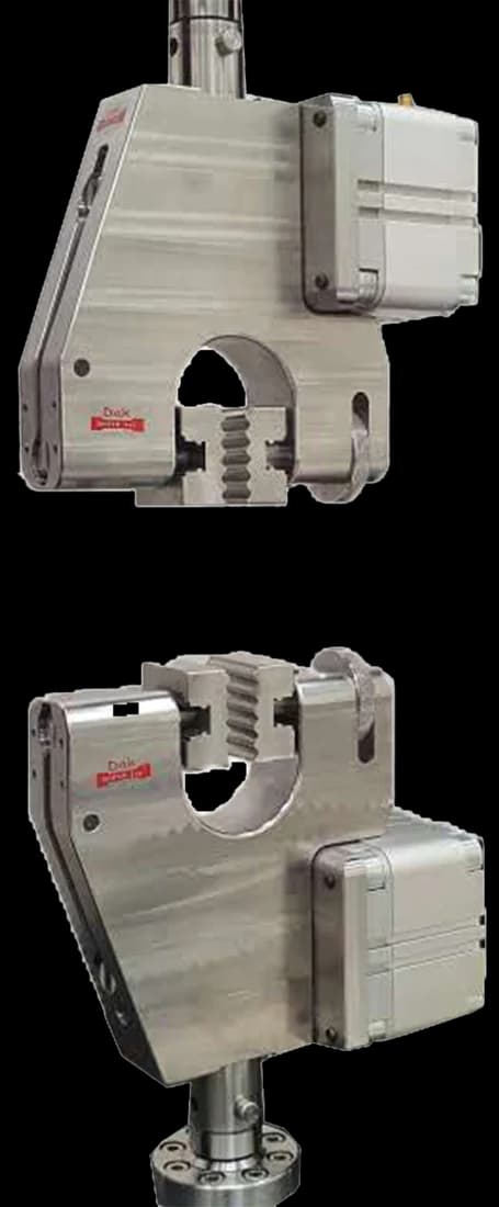
Standard 25 mm
Pneumatic Vice Action Grip
Pneumatic vice action grips clamp the full specimen width at a constant, even pressure — which is what stops one side slipping or tearing before the other.
Specifications
Testing standard
Geosynthetics — Wide-width tensile test
Written and technically reviewed by Dak System Inc. engineeringLast reviewed
ISO 10319 is the wide-width tensile test for geosynthetics. The specimen is 200 mm wide and shorter than it is wide, because a narrow strip of geotextile contracts as it is pulled and reads far below the material's real capability. Results are reported as force per unit width, not as stress.
From the test method to your testing system
Explore the DAK machines already listed for ISO 10319, then review the grips, measurement and setup requirements below.
 Universal Testing MachineSeries 7200Explore the machine →
 Universal Testing MachineSeries 9000Explore the machine →
01Understand the method
A strip of geosynthetic 200 mm wide, and shorter along the pull than it is wide, is clamped across its full width and extended at a strain rate of (20 ± 5) % per minute in the gauge length until it fails. The method sets the jaws 100 mm apart, so that is a crosshead speed of 20 mm/min, the tolerance band running from 15 to 25 mm/min. Products that stretch 5 % or less — glass reinforcement is the example the standard gives — are the exception: rather than a strain rate, the speed is reduced until the specimen breaks in (30 ± 5) s. Force is recorded against strain measured on the specimen itself. From the curve come three reported values: the maximum load per unit width in kilonewtons per metre, the strain at that maximum, and the secant stiffness at whatever strain the specification names. Procedures for both conditioned and wet specimens are included, and the machine and cross-machine directions are tested separately.
The load a geosynthetic can carry per metre of width, and how much it stretches getting there — which is what reinforcement design actually consumes. A reinforced soil wall or an embankment over soft ground is designed around force per metre and a stiffness at working strain, not around a stress, so the method reports in the units the designer uses. The standard describes itself as an index test: it gives design parameters and a basis for acceptance under controlled conditions, and does not model the interaction between the geosynthetic and the soil around it.
02Prepare the specimen and test settings
The specimen is wider than its gauge length on purpose. That is the entire reason the method exists.
It is an index test by its own description. It gives design parameters for reinforcement and a basis for acceptance, and it is not a model of soil interaction.
03Build the test setup on a DAK machine
Capacity that follows the product — a reinforcement geogrid can exceed a hundred kilonewtons per metre, so the frame is sized for the strongest item in the range. Grips must hold the full 200 mm width evenly, and for high-strength products a roller or capstan arrangement is effectively required, because a flat jaw clamped hard enough to hold the load will crush the fibres at the jaw line and cause the specimen to fail there. Strain must be measured on the specimen, since on the nominal 60 mm gauge the standard defines, grip take-up is a large fraction of crosshead travel. Speed itself asks little of the frame — 20 mm/min is slow — but it has to be held constant to the tolerance.
Pneumatic vice action grips clamp the full specimen width at a constant, even pressure — which is what stops one side slipping or tearing before the other.
SpecificationsDak verifies against whichever standard the method names, and where a class applies our frames sit a class tighter than it asks.
| The method asks for | Dak supplies | |
|---|---|---|
| Capacity | Moderate to high — a reinforcement geogrid can exceed 100 kN/m, so frame capacity follows the product | Load cells from 1 kg to 60 ton on the Series 7200, and 0.5 to 100 kN on the Series 9000 |
| Force accuracy | ISO 7500-1 Class 1 over the working range | ISO 7500-1 Class 0.5 — a class tighter than the method asks |
| Strain measurement | An extensometer of the class the method specifies | Certified to ISO 9513 Class 1 and ASTM E83 — non-contact video, clip-on and high-elongation |
| Gripping | Wide-width grips clamping the full 200 mm specimen width, with roller or capstan clamping for high-strength products | Our eccentric roller grips or split capstan grips, built to the specimen |
| Environment | 23 ± 2 °C standard laboratory atmosphere | 3009 series chambers, −150 °C to +400 °C — temperature only |
04Run the test
05Calculate, report and interpret
Tmax = Fmax / B
Force per metre of width. Reinforcement design works in these units directly, which is why nothing is divided by a thickness.
εmax = (ΔL / L₀) × 100
Measured on the specimen. Crosshead travel includes grip take-up, which is a large fraction of a short gauge length.
J = T / ε at a specified strain
Quoted at a stated strain — commonly 2 % or 5 % — and the strain must be stated with the value or the number means nothing.
Taking strain from the crosshead, which overstates elongation and understates stiffness by a margin that grows as the gauge length shrinks. Quoting a secant stiffness without the strain it was evaluated at, which makes the figure unusable rather than merely incomplete. Accepting jaw breaks into the data set, where they always read low. And testing only dry specimens for a product that will spend its service life saturated, when the standard supplies a wet procedure precisely because some materials lose strength when wet.
06Compare methods and find answers
| ISO 10319 | ASTM D4595/D4595M | |
|---|---|---|
| Family | ISO | ASTM |
| Specimen | 200 mm wide, short gauge | 200 mm wide, comparable aspect |
| Reported | kN/m and secant stiffness | Force per unit width and modulus |
| Wet procedure | Included | Addressed in the method |
Very close in principle, and both exist for the same reason — a narrow strip reads low. Cite the one the specification names, since geosynthetic acceptance documents are written against a particular designation.
It is the wide-width tensile test for geosynthetics — an index method covering woven and nonwoven geotextiles, geocomposites, knitted geotextiles, geonets, geomats and metallic products, and applicable to geogrids with adjusted specimen dimensions. It measures the load-elongation behaviour of a 200 mm wide strip pulled at (20 ± 5) % per minute in the gauge length — 20 mm/min on the 100 mm jaw separation — and reports maximum load per unit width, strain at maximum load and secant stiffness.
Because a narrow strip of geotextile contracts inwards as it is stretched. The yarns at the edges pull towards the centre, the specimen waists, and the recorded strength falls well below what the material would deliver in the ground where it is continuous in every direction. Making the specimen 200 mm wide and shorter than it is wide prevents that contraction, which is why the aspect ratio looks wrong and is deliberate.
Because geotextile thickness is not a meaningful denominator. A nonwoven compresses substantially under the pressure used to measure it, so any stress calculated from it would depend on how hard the gauge was pressed. Reinforcement design also works directly in force per metre of width — that is the quantity a retaining wall or a reinforced embankment is designed with — so normalising by width rather than area matches both the measurement and the use.
Because the gauge length is short and grip take-up is not. When the specimen is only around 100 mm between clamps, the settling of the fabric in the jaws and any slippage represent a large fraction of the total crosshead movement. Strain calculated from crosshead travel therefore overstates elongation substantially and understates stiffness, which matters because secant stiffness at a stated strain is one of the primary reported values.
It is the tensile force per unit width divided by the strain, evaluated at a specified strain — commonly 2 % or 5 %. Because a geosynthetic's load-strain curve is not straight, the value depends entirely on where it is taken. A stiffness quoted without the strain it belongs to is not an incomplete number, it is an unusable one, and specifications always name the strain.
Because many geosynthetics spend their whole service life saturated, buried in soil below the water table or in drainage applications, and some materials lose strength when wet. Testing only conditioned dry specimens would report a property the product never has in service. The method therefore defines how to saturate and test wet specimens so the difference can be quantified rather than assumed.
It is rejected. A break at the clamp line reports the damage done by the grips, not the strength of the fabric, and it always reads low. High-strength reinforcement products are particularly prone to it, which is why roller or capstan clamping is used for them — a flat jaw tight enough to hold the load will crush the fibres where it grips. A high rejection rate is a signal about the clamping, not the material.
Discuss your specimen, test requirements and reporting needs with DAK engineering.
This page describes the method as practised. The governing text is the current edition from the issuing body. Tell us what you are testing and we will answer with the machine, the fixture and a quotation.