
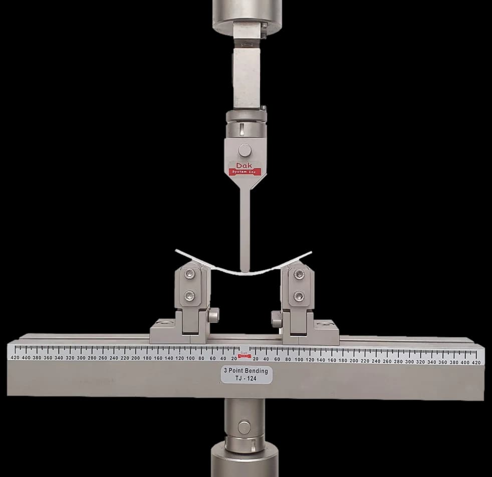
Adjustable spanTJ-124
Three Point Bend Fixture
A three-point bend fixture with the short span the method specifies. Span-to-thickness is the whole variable here — set it on the fixture, never assume it.
Specifications
Testing standard
Fibre-reinforced plastic composites — Determination of apparent interlaminar shear strength by short-beam method
Written and technically reviewed by Dak System Inc. engineeringLast reviewed
ISO 14130 determines the apparent interlaminar shear strength of fibre-reinforced plastic composites by loading a short, thick beam in three-point bending. The word apparent is doing real work: the standard states the method is not suitable for determining design parameters and is for screening or quality control.
From the test method to your testing system
Explore the DAK machines already listed for ISO 14130, then review the grips, measurement and setup requirements below.
 Universal Testing MachineSeries 7200Explore the machine →
 Universal Testing MachineSeries 9000Explore the machine →
01Understand the method
A short, thick coupon is placed centrally on two supports and loaded at mid-span in three-point bending at 1 mm/min (0.04 in./min) until it fails. The failure force, the specimen width and its thickness give the apparent interlaminar shear strength. The span and the roller radii are set to what the method specifies and are reported with the result, because the value depends on both. Every failed coupon is examined afterwards, since only a clean interlaminar crack makes the arithmetic mean anything.
How well the plies of a laminate hold to one another — the property that governs delamination, which is how composite structures usually come apart. The short span is the whole design of the test: in three-point bending the peak bending stress rises with span while the shear stress does not, so a long beam breaks in tension on its underside, and shortening the span tips the balance until the interlaminar plane fails first. It is quick and discriminating, which is why it is the usual incoming-inspection test for laminates.
02Prepare the specimen and test settings
The span-to-thickness ratio is deliberately small so the beam fails in shear between the plies rather than in bending.
This is a quality-control number, not a design allowable. Quoting it as an interlaminar shear design value is the misuse the word apparent exists to prevent.
03Build the test setup on a DAK machine
Modest force — a short-beam coupon commonly fails between a few hundred newtons and a few kilonewtons — with a crosshead holding 1 mm/min and a three-point fixture whose span is settable and whose rollers are the specified radii: 5 mm ± 0,2 mm on the loading member and 2 mm ± 0,2 mm on the supports. The span is the parameter that decides the answer, and the method fixes it at five times the specimen thickness, which on the standard 2 mm × 10 mm × 20 mm coupon is a 10 mm span. It is set deliberately and recorded rather than inherited from whatever the fixture was last used for. The speed travels with the result: the standard has the test report cite the method and the rate together, so a run at 1 mm/min is reported as ISO 14130/1. The machine follows ISO 5893, with force indicated to better than ±1 % of full scale. Nothing else is demanding — no extensometer and no strain measurement.
A three-point bend fixture with the short span the method specifies. Span-to-thickness is the whole variable here — set it on the fixture, never assume it.
SpecificationsDak verifies against whichever standard the method names, and where a class applies our frames sit a class tighter than it asks.
| The method asks for | Dak supplies | |
|---|---|---|
| Capacity | Low to moderate — a short-beam coupon commonly fails between a few hundred newtons and a few kilonewtons | Load cells from 1 kg to 60 ton on the Series 7200, and 0.5 to 100 kN on the Series 9000 |
| Force accuracy | ISO 7500-1 Class 1 over the working range | ISO 7500-1 Class 0.5 — a class tighter than the method asks |
| Gripping | A three-point bend fixture at the short span the method specifies, with rollers of the specified radii | Our bend fixtures, built to the specimen |
| Environment | 23 ± 2 °C standard laboratory atmosphere | 3009 series chambers, −150 °C to +400 °C — temperature only |
04Run the test
05Calculate, report and interpret
τ = 0,75 × F / (b × h)
The 0,75 is the parabolic shear distribution through a rectangular section — the peak shear stress at mid-thickness is 1,5 times the mean, and the mean here is F/2 over the area.
Shear stress is independent of span; bending stress rises with it
That asymmetry is the whole method. Shorten the span far enough and shear wins the race to failure.
Quoting the result as a design allowable. The scope says plainly that the method is not for design parameters and is for screening or quality control, and the word *apparent* in the title is the same warning in one word — the stress state under a loading nose on a short beam is not pure shear. After that: not examining the failure mode, so flexural and bearing failures average in silently; and omitting the span from the report, which makes the value unreproducible, because two laboratories at different span-to-thickness ratios will get different numbers and both will be right about what they measured. A quieter one is inheriting whatever span the fixture was last set to, which gives a result that is internally consistent and comparable with nothing.
06Compare methods and find answers
| ISO 14130 | ASTM D2344/D2344M | |
|---|---|---|
| Principle | Short-beam three-point bending | Short-beam three-point bending |
| Reports | Apparent interlaminar shear strength | Short-beam strength |
| Design use | Explicitly excluded | Explicitly cautioned |
| Failure mode | Must be interlaminar to be valid | Must be interlaminar to be valid |
The same test in two families, and both are careful about the same thing: the number is comparative. Keep to one within a data set, since specimen dimensions and span ratios differ.
It is the ISO short-beam method for the apparent interlaminar shear strength of fibre-reinforced plastic composites. A short, thick coupon is loaded in three-point bending until it fails between the plies, and the failure force gives a shear strength. It suits thermoset and thermoplastic matrices alike, provided interlaminar shear failure is actually obtained.
Because span decides which failure wins. In three-point bending the peak bending stress rises with span while the shear stress does not, so a long beam breaks in tension on its underside. Shortening the span far enough tips the balance until the interlaminar plane — the weakest thing in a laminate — gives way first. The short span is not a convenience, it is the method.
That the number describes the coupon rather than the material. The stress state under a loading nose on a short beam is not pure shear: there is through-thickness compression, local crushing and a stress concentration, all mixed into one failure force. The standard is explicit that the result is not suitable for determining design parameters and is for screening materials or quality control.
When the coupon did not fail interlaminarly. If it broke in tension on the lower face, that is a flexural result. If it crushed under the loading nose, that is a bearing result. Either way the arithmetic still produces a number, and that number is not an interlaminar shear strength. Examining every failed coupon is what separates the two.
From the shape of the shear stress distribution through a rectangular section, which is parabolic with a peak at mid-thickness equal to one and a half times the mean. Combined with the fact that each support carries half the applied force, that gives three quarters of F over the cross-sectional area. It is geometry, not a fudge factor.
Because the result depends on it. Two laboratories testing the same laminate at different span-to-thickness ratios will get different numbers, and neither is wrong — they measured under different conditions. Reporting the span and the roller radii is what makes a value reproducible rather than merely plausible.
Cautiously. Both use short-beam three-point bending and both warn against design use, but specimen dimensions and span ratios differ between them, so results should not be pooled. Cite the standard alongside the figure and keep a data set to one method.
Discuss your specimen, test requirements and reporting needs with DAK engineering.
This page describes the method as practised. The governing text is the current edition from the issuing body. Tell us what you are testing and we will answer with the machine, the fixture and a quotation.