Resistance welding — Destructive testing of welds — Specimen dimensions and procedure for tensile shear testing resistance spot and embossed projection welds
Written and technically reviewed by Dak System Inc. engineering·Last reviewed
ISO 14273 pulls a lap joint containing a single resistance spot weld along the plane of the sheets and reports the maximum force the joint carried. It is a force, not a stress, and it is always reported with the failure mode: a button pull-out means the nugget beat the sheet, an interfacial break means it did not. The current edition is ISO 14273:2016.
Two overlapping metal sheets joined by a single resistance spot weld are pulled apart along the plane of the sheets. Each sheet is gripped at its free end, packing shims are fitted so the line of pull passes as nearly as possible through the weld, and the crosshead separates the grips until the joint fails. The maximum force recorded is the tensile shear force of that weld. It is the most common destructive weld test in a press shop because it is the cheapest one that produces a number.
What it measures, and why it matters
The result is a force, not a stress. There is no meaningful area to divide by: the nugget is a rough disc whose diameter is not known until the specimen is sectioned or peeled, and the load path through a lap joint is not pure shear in any case.
That force is used two ways. Against an acceptance value in a welding procedure specification it says whether the joint passes. Plotted against welding current, with weld time and electrode force fixed, it maps the usable current range — the window between too little heat for a sound nugget and enough heat for expulsion. Drawing that window is the practical goal of most spot-welding development work. Failure mode is recorded alongside the force and carries as much information: a plug or button pull-out means a nugget stronger than the sheet around it, while an interfacial failure across the weld face points at an undersized or defective nugget even when the force looks acceptable.
Specimen, and the geometry that decides where it breaks
The tabulated dimensions exist to force failure at the weld. A specimen that is too narrow yields in the parent sheet and measures the steel instead of the joint.
Joint
Two overlapping sheets with one spot or embossed projection weld
Material
Any metallic material
Sheet thickness
0.5 mm to 10 mm
Maximum weld diameter
7√t, with t the sheet thickness in mmAbove that diameter the tabulated specimen width is no longer wide enough to keep failure in the weld.
Width, overlap and free length
Tabulated against sheet thickness in the standard
Weld position
Central in the overlap
Coating
Left on — never removed before testPracticeThe coating changes the contact resistance and the nugget growth, so a stripped specimen no longer represents the joint the line produces.
Cut without heating the sheet
DakA torch or a hot abrasive cut alters the metallurgy beside the nugget, and the damage is invisible in the force trace — it just reads low.
Dissimilar-thickness and dissimilar-material joints are common in a modern body shop and are outside the tabulated geometry. Agree the specimen with the customer before cutting, and record what was agreed, because two laboratories will otherwise choose differently and their numbers will not compare.
Rate, and what the machine records
Loading
Continuous tensile loading to failure
Rate
As specified in the standard; the rate is not publicly quotableThe test rate sits in the purchased text. Fix it, record it, and keep it the same across a weld-current series — the comparison is only valid if the rate did not move.
Reported
Maximum force, in N or kN, plus the failure mode
Sampling rate
High enough to catch an abrupt peakDakA spot weld gives no warning and does not neck. A slow logger reads a peak below the real one and the loss looks like a weld defect.
What is calculated, and what deliberately is not
Tensile shear force—
The maximum force recorded before the joint fails
Reported as a force. No division by area is performed.
Why there is no shear stress—
Nugget area is unknown until the weld is destroyed
The nugget is a rough disc whose diameter is only known after sectioning or peeling, and a lap joint is not in pure shear anyway. A quoted MPa figure for a spot weld is an invention.
Weldability lobe—
Tensile shear force plotted against welding current
lower bound
the current below which the nugget is too small
upper bound
the current at which expulsion begins
Weld time and electrode force are held constant while current is stepped. The width of that window is what most spot-welding development is trying to widen.
How the test runs
01Weld the coupons on the production or laboratory schedule under test.
02Cut the specimens to the tabulated width and overlap without heating the sheet.
03Check that the weld sits centrally in the overlap.
04Measure and record sheet thickness and, where required, weld diameter.
05Fit packing shims of the sheet thickness into both grips.
06Clamp one sheet in each grip so the line of pull passes through the weld.
07Check that the two grips lie in the same vertical plane.
08Load continuously to failure at the specified rate.
09Record the maximum force.
10Examine the broken specimen and classify the failure mode.
11Report force and failure mode together, never one without the other.
The shims are not optional and they are not a convenience. Without them the two sheets are offset by their own thickness, the specimen rotates as load builds, and the joint is peeled open rather than sheared. The number that comes out is low, repeatable, and wrong.
Grips and fixtures for this method
TJ-144
Heavy Duty Hydraulic Grips
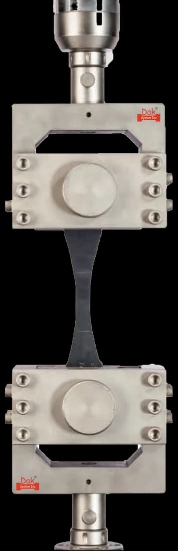
Flat, serrated faces wide enough to take the full specimen width, closing on a coated strip without slipping. Hydraulic closure keeps the clamping force the same from specimen to specimen, which matters across a weld-current series where the only variable is meant to be the current.
Where the specimen is wide and the force is modest, a 100 mm vice-action grip takes the whole width in one clamped face. Packing shims still have to be fitted; the grip does not remove the offset.
A load cell sized for the joint rather than the frame. Thin-sheet spot welds fail in single-digit kilonewtons, and a cell chosen for a 600 kN frame throws away the resolution the peak needs.
Parent material, grade, coating and thickness of both sheets
Welding parameters: current, weld time, electrode force and electrode geometry
Specimen width, overlap and free length
Weld diameter where it was measured, and how
Test rate
Maximum force for each specimen
Failure mode for each specimen
Mean and the number of specimens
Any departure from the tabulated geometry, and why
What the machine must be capable of
A single spot weld in thin automotive sheet fails somewhere between a few kilonewtons and roughly 30 kN; thicker sheet takes more. A 50 to 100 kN frame with clean resolution at the bottom of its range covers most of this work, and force accuracy to ISO 7500-1 Class 1 is the normal requirement.
Grips must hold a flat, coated strip without slipping and without bending it. Hydraulic wedge or vice-action grips with serrated faces are usual, and the faces have to be wide enough for the full specimen width. The critical detail is the packing: shims of the same thickness as the sheet go in each grip so the two sheets are loaded in line, and without them the specimen rotates under load and the test measures a peel rather than a shear. Elongation is not part of the result, so no extensometer is needed — but the data rate has to be fast enough to catch a peak that arrives abruptly, because a spot weld does not neck.
What goes wrong in practice
Omitted or wrong-thickness packing shims are the commonest error, and they lower the recorded force in a way that looks like a welding problem rather than a fixturing one. Grips misaligned in the vertical plane do the same thing more subtly. Specimens cut with a torch or an abrasive wheel that heats the sheet change the metallurgy beside the nugget. And recording only the force, without the failure mode, throws away half of what the test produced.
The three destructive spot-weld tests
They load the same nugget in three different directions and answer three different questions. A specification that names one is not satisfied by another.
Tensile shear (ISO 14273)
Cross tension (ISO 14272)
Mechanised peel (ISO 14270)
Load direction
Along the plane of the sheets
Through the sheet thickness
Progressive peel from one edge
Sheet thickness covered
0.5 mm to 10 mm
0.5 mm to 3 mm
0.5 mm to 3 mm
Typical use
Process setup and routine acceptance
Ductility and crash-relevant behaviour
Nugget quality and coating effects
Fixture
Flat grips with packing shims
A dedicated cross-tension jig
A dedicated peel jig
Result
Maximum force plus failure mode
Peel force plus failure mode
A joint can pass in tensile shear and fail in cross tension. Shear loads the nugget in its strongest direction; cross tension opens it. Where crash performance matters, the shear figure alone is not evidence.
Questions we are asked about this test
What is ISO 14273?+
ISO 14273 is the international method for tensile shear testing of resistance spot and embossed projection welds. A lap joint containing one weld is pulled along the plane of the sheets until it fails, and the maximum force is reported together with the failure mode. The current edition is ISO 14273:2016, which superseded ISO 14273:2000 and narrowed the scope by dropping seam welds from the title.
Why is the result a force and not a stress?+
Because there is no area to divide by. The weld nugget is a rough disc whose diameter is not known until the specimen is sectioned or peeled apart, and the stress state in a lap joint is a mixture of shear, tension and bending rather than pure shear. Every acceptance criterion for spot welds is written as a force for this reason, and a shear strength in MPa quoted for a spot weld has been invented somewhere along the way.
What are the packing shims for?+
They put the two sheets in line. Without them the sheet clamped in the upper grip and the sheet clamped in the lower grip are offset by their own thickness, so the specimen rotates as load builds and the weld is progressively peeled rather than sheared. The result is low and repeatable, which is what makes it dangerous: it looks like a welding problem and it is a fixturing one. The shims are the same thickness as the sheet and go in both grips.
What does the failure mode tell you?+
As much as the force. A plug or button pull-out, where the nugget tears a hole out of one sheet and stays attached to the other, means the weld is stronger than the parent metal around it. An interfacial failure, where the joint parts flat across the weld face, means the nugget was undersized or defective even if the force looked acceptable. Reporting force without failure mode discards half the test.
How does it differ from ISO 14272 cross tension?+
Direction. Tensile shear loads the nugget along the plane of the sheets, which is its strongest direction, while cross tension pulls the sheets apart through the thickness and opens the weld. A joint can pass in shear and fail in cross tension, which is why crash-relevant work runs both. ISO 14272 also covers a narrower thickness range, 0.5 mm to 3 mm against 0.5 mm to 10 mm here, and needs a dedicated jig rather than flat grips.
What machine does it need?+
A tensile frame of 50 to 100 kN with force accuracy to ISO 7500-1 Class 1 covers most automotive sheet work, and clean resolution at the bottom of the range matters more than headline capacity because thin-sheet welds fail in single-digit kilonewtons. Grips must hold a flat coated strip without slipping, and the data rate has to be high enough to catch an abrupt peak, because a spot weld does not neck before it goes.
Should the zinc coating be removed before testing?+
No. The coating is part of the joint. Zinc, zinc-iron and aluminium-silicon coatings change the contact resistance at the faying surface and therefore change how the nugget grows, which is exactly what the test is measuring. A specimen stripped back to bare steel no longer represents anything the production line makes.
Can it be used on aluminium or on dissimilar joints?+
The scope is any metallic material, so aluminium is covered, and in practice aluminium spot welds are tested this way routinely. Dissimilar-thickness and dissimilar-material stack-ups are a different matter: the tabulated specimen geometry assumes two sheets of the same thickness, so the geometry has to be agreed between the parties and recorded in the report. Without that agreement two laboratories will choose differently and their figures will not compare.

This page describes the method as practised. The governing text is the current edition from the issuing body. Tell us what you are testing and we will answer with the machine, the fixture and a quotation.