
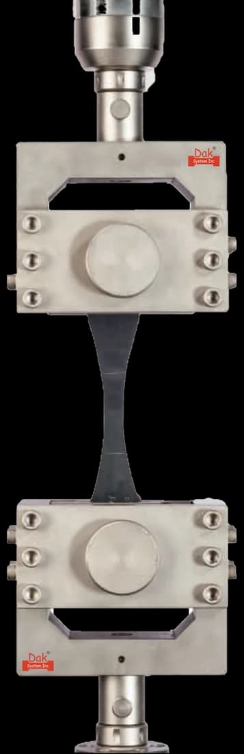
TJ-144
Heavy Duty Hydraulic Grips
Heavy duty hydraulic wedge grips hold a constant clamping force as the coupon thins slightly under load, which mechanical wedges do not always manage at composite failure loads.
Specifications
Testing standard
Standard Test Method for In-Plane Shear Response of Polymer Matrix Composite Materials by Tensile Test of a ±45° Laminate
Written and technically reviewed by Dak System Inc. engineeringLast reviewed
ASTM D3518 obtains the in-plane shear response of a composite by pulling a ±45° laminate in simple tension. No shear fixture is involved — the lay-up does the work, because a ±45° laminate loaded along its axis puts each ply into shear. Biaxial strain measurement turns the tensile data into a shear stress-strain curve.
From the test method to your testing system
Explore the DAK machines already listed for ASTM D3518, then review the grips, measurement and setup requirements below.
 Universal Testing MachineSeries 7200Explore the machine →
 Universal Testing MachineSeries 9000Explore the machine →
01Understand the method
A straight-sided coupon is cut from a balanced, symmetric ±45° laminate and pulled in simple tension at about 2 mm/min — in ordinary wedge grips, with no shear fixture of any kind. Strain is measured in both the longitudinal and the transverse directions. The axial stress is halved to give the in-plane shear stress, which is an exact geometric consequence of loading a ±45° lay-up along its axis, and the shear strain is obtained as the difference between the two measured strains. From that pair comes a full shear stress-strain curve, and from its initial slope the shear modulus.
In-plane shear modulus and shear strength are among the properties a laminate cannot be designed without. Every bolted joint, every ply drop, every place where load passes from one part of a structure into another puts the laminate into shear, and the matrix rather than the fibre carries it — which makes shear the property most sensitive to cure state, void content and moisture. What makes this method valuable out of proportion to its simplicity is that it needs no fixture at all, so a laboratory equipped only for tensile testing can produce shear data on the same day it produces tensile data.
02Prepare the specimen and test settings
The lay-up IS the fixture. That is what makes this the cheapest shear test there is, and also what limits it.
Shear stress in this test is exactly half the applied axial stress. It is a geometric consequence of the ±45° lay-up, not an approximation — but forgetting the factor of two doubles every reported shear stress.
03Build the test setup on a DAK machine
Force measurement across a range from a few kilonewtons to perhaps thirty, a crosshead holding 2 mm/min, and — the distinguishing requirement — two strain channels recorded simultaneously with force. Alignment matters as it does for any tensile coupon, since eccentricity introduces bending. The subtler requirement is stroke and strain capacity: a ±45° coupon can extend a great deal before it fails, and both the crosshead travel and the strain measurement have to accommodate that or the test ends for an instrumentation reason rather than a material one.
Heavy duty hydraulic wedge grips hold a constant clamping force as the coupon thins slightly under load, which mechanical wedges do not always manage at composite failure loads.
Specifications
Universal parallel wedge grips where the coupon width and failure load sit within their range.
SpecificationsDak verifies against whichever standard the method names, and where a class applies our frames sit a class tighter than it asks.
| The method asks for | Dak supplies | |
|---|---|---|
| Capacity | Moderate — a ±45° carbon coupon commonly fails between 5 and 30 kN | Load cells from 1 kg to 60 ton on the Series 7200, and 0.5 to 100 kN on the Series 9000 |
| Force accuracy | unknown — ASTM E4 is not among this method's referenced documents, which name no force-verification standard and no accuracy class | ISO 7500-1 Class 0.5 — the method sets no class of its own |
| Strain measurement | An extensometer of the class the method specifies | Certified to ISO 9513 Class 1 and ASTM E83 — non-contact video, clip-on and high-elongation |
| Gripping | Ordinary tensile wedge grips — the shear state comes from the lay-up, not from a fixture | Our self-tightening serrated wedge grips, with V-jaws for round specimens, built to the specimen |
| Environment | 23 ± 2 °C standard laboratory atmosphere | 3009 series chambers, −150 °C to +400 °C — temperature only |
04Run the test
05Calculate, report and interpret
τ₁₂ = σₓ / 2
The factor of two comes from resolving the axial load onto planes at 45°. It is exact for this lay-up, and omitting it is the commonest error in the whole method.
γ₁₂ = εₓ − εᵧ
Subtracting a negative transverse strain adds it. This is why two gauges are mandatory.
G₁₂ = Δτ₁₂ / Δγ₁₂ over the defined range
Forgetting to halve the axial stress is the commonest error and the hardest to catch, because a shear stress twice its true value is still an entirely plausible number. Fitting only one strain gauge is the commonest reason a test has to be repeated outright — there is no partial result. Beyond those, the honest limitation is ply rotation: at large strains the fibres turn away from ±45° toward the loading axis, so the geometry producing the shear state is itself changing, and a modulus taken early is more trustworthy than a strength taken late. Reporting a stress at a strain limit as though it were a rupture strength conflates two different quantities.
06Compare methods and find answers
| ASTM D3518 | ASTM D7078 | |
|---|---|---|
| Fixture | None — ordinary tensile grips | V-notched rail shear fixture |
| Lay-up | Must be ±45° | Any lay-up |
| Shear state | Approximate; plies rotate at large strain | Cleaner and more uniform |
| Cost and speed | Low — the cheapest shear test available | Higher; needs the fixture |
D3518 is excellent for screening and for material qualification where a ±45° laminate is representative. Where a design allowable is needed, or the lay-up is not ±45°, D7078 gives the cleaner shear state and is the better answer.
It is the ASTM method for in-plane shear response of a composite, obtained by pulling a ±45° laminate in simple tension. There is no shear fixture — the lay-up produces the shear state, because a ±45° laminate loaded along its axis puts each ply into shear.
It is a geometric consequence of resolving the applied load onto planes at 45° to it. For this specific lay-up the relationship is exact, not an approximation. Forgetting the factor of two doubles every reported shear stress, and because the resulting number is still plausible it can survive a long way into a data set.
Because shear strain is the difference between the longitudinal and transverse strains, and the transverse one is negative. A single gauge cannot produce the result at all — not a less accurate result, but no result. This is the most common reason a D3518 test has to be repeated.
The shear state is approximate rather than pure, and it degrades as the test proceeds. At large strains the fibres rotate away from ±45° toward the loading axis, so the geometry that produced the shear state is progressively changing. That is fine for screening and for modulus, and it is why the method is less suited to producing a design allowable.
Because a ±45° laminate is remarkably ductile in this direction — the plies scissor rather than the fibres breaking, and the coupon can reach very large strains without a clean rupture. That is why the method sets a strain limit as an alternative ending, and why a stress at that limit and a strength at rupture are different quantities that must be labelled.
Usually not. A ±45° laminate is compliant and comparatively low in axial strength, so wedge grips seldom damage it — which is another reason this test is quick and cheap. If failures do occur at the grips, tabs are the answer, but it is not the default here as it is for a unidirectional coupon.
When you need a design allowable, when the lay-up is not ±45°, or when the material reaches strains large enough that ply rotation makes the D3518 shear state questionable. D7078's V-notched rail shear fixture produces a cleaner and more uniform shear state, at the cost of the fixture and the preparation.
Discuss your specimen, test requirements and reporting needs with DAK engineering.
This page describes the method as practised. The governing text is the current edition from the issuing body. Tell us what you are testing and we will answer with the machine, the fixture and a quotation.