Compression Anvils
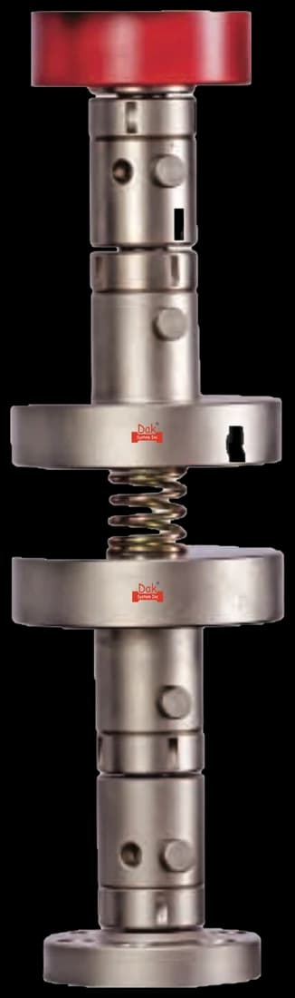
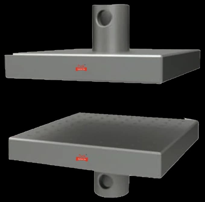
Flat parallel anvils, lubricated or bonded as the method requires. Their parallelism matters directly: an anvil out of true compresses one side of a rubber disc first and the fourth-cycle curve carries that error.
SpecificationsTesting standard
Rubber, vulcanized or thermoplastic — Determination of compression stress-strain properties
Written and technically reviewed by Dak System Inc. engineeringLast reviewed
ISO 7743 measures the compression stress-strain properties of rubber. A short cylinder is squeezed between two flat plates through four uninterrupted cycles, and the FOURTH is the one read — so the reported curve describes settled rubber rather than fresh rubber. It gives compression stress at defined strains, the secant modulus, and stiffness for product-form testing.
A short rubber cylinder is placed between two flat, parallel metal plates and squeezed. The moving platen advances at a fixed rate to a set compression, then reverses to zero, and this is repeated for four uninterrupted cycles. Force and platen separation are recorded throughout. The fourth cycle is the one read, so the reported curve describes settled rubber rather than fresh rubber.
The method reports compression stress at defined strains, the derived secant modulus, and — on the product route — stiffness at a stated compression. Those figures size mounts, bushes, bearing pads and seals, where a designer needs force per millimetre of squash rather than a tensile number. They also serve lot release, since a stiffness shift between batches exposes a filler or cure change no hardness reading catches. Because stiffness depends on shape factor as much as on compound, values transfer between geometries only through calculation.
Report the shape factor with the result, always. Two laboratories testing the same compound on different specimen types will disagree, and both will be right — stiffness is a property of the compound and the geometry together.
σ = F / A₀
ε = (h₀ − h) / h₀ × 100
E_s = σ at a stated strain / that strain
Derived rather than measured, and quoted at the strain it was taken at. A rubber's compression curve is markedly non-linear, so a single modulus without a strain is not usable.

Flat parallel anvils, lubricated or bonded as the method requires. Their parallelism matters directly: an anvil out of true compresses one side of a rubber disc first and the fourth-cycle curve carries that error.
Specifications
Direct compression platens where the specimen or the product form needs a larger bearing face than the standard anvils provide.
SpecificationsForce demand is modest. Test piece A at 25 % compression usually draws a few hundred newtons up to about 2 kN, and hard bonded rubbers reach roughly 5 kN, so a 1–2 kN cell covers routine work while method D product tests are sized case by case. Force must be graded to ISO 5893 grade 1, equivalent to ISO 7500-1 Class 1.
Rate is fixed at 10 ± 2 mm/min for both the compression and the release stroke. Rubber is viscoelastic, so a faster return stroke inflates the hysteresis loop and corrupts the fourth-cycle reading. The frame must reverse cleanly at the turning point rather than dwelling there.
No extensometer is fitted. Deformation is taken as platen separation, but it must be determined to ±0,02 mm with the compliance of the load cell and the frame corrected out — ±0,2 % of test-piece height for products shorter than the standard test piece. Uncorrected frame stretch is the single largest error in this method.
The fixture is a pair of polished flat plates, lubricated, bonded or bare according to method, at least as large as the test piece for bonding and at least 20 mm larger for lubrication; a finish no worse than Ra 0,4 µm suits methods A and D. Strain runs 0 to 25 % for methods A, B and C and 0 to 30 % for method D. Optional temperature work spans −75 °C to 250 °C and needs a chamber.

Erratic slip is the commonest fault: a lubricant film of the wrong viscosity — the method calls for a silicone or fluorosilicone fluid near 0,01 m²/s — breaks down mid-stroke and the trace steps. Bare plates instead restrain the ends, so the piece barrels and biaxial compression reads stiff. Ring-shaped products trap air unless the platens are vented, giving a false rising force. High set after the four cycles means the piece was over-strained or undercured, and it is a rejection, not a result.
| ISO 7743 rubber | ASTM D695 plastics | ASTM E9 metals | |
|---|---|---|---|
| Cycles | Four, fourth read | One | One |
| Failure | None — it is elastic | Yield or flatten | Yield or fracture |
| Key output | Stress at defined strains | Offset yield | Offset yield |
| Geometry dependence | Total — via shape factor | Controlled by slenderness | Controlled by slenderness |
Rubber is the outlier and for a good reason: it does not yield, so there is no strength to find. What the designer needs is force per millimetre of squash at the geometry actually used, which is why shape factor sits at the centre of this method and nowhere else.
It is the international standard for the compression stress-strain properties of vulcanised and thermoplastic rubber. A short cylinder is compressed between flat plates through four uninterrupted cycles, and the fourth is read — giving compression stress at defined strains, the secant modulus, and stiffness on the product route.
Because filled rubber softens on first straining and never fully recovers — the Mullins effect. A first-cycle curve therefore describes a state the material will never be in again once it is in service. Three conditioning cycles take the softening out, so the fourth describes settled rubber, which is what a mount or bush will actually behave like.
It is the loaded area divided by the force-free area — essentially how squat the specimen is. A squat disc bulges less and is therefore far stiffer than a slender one of the same compound. Because of that, a compression stiffness figure is a property of the compound AND the geometry, and transfers between shapes only through calculation.
A great deal. Lubricated plates let the rubber bulge freely; bonded plates restrain it and raise the apparent stiffness substantially. The two conditions give different curves for the same compound, so the plate condition is reported with the result rather than being an operator's convenience.
Because rubber does not fail in compression — it stores the energy and gives it back. There is no yield and no fracture to find, so the useful outputs are stress at defined strains and the derived secant modulus. That is also why this method cycles and reads a settled curve rather than pushing to a failure that never comes.
Because a rubber's compression curve is markedly non-linear — it stiffens as it is squashed. A single modulus figure therefore describes only the point it was taken at, and quoting one without its strain is as incomplete as quoting a creep modulus without its time.
Dak verifies against whichever standard the method names, and where a class applies our frames sit a class tighter than it asks.
| The method asks for | Dak supplies | |
|---|---|---|
| Capacity | Standard test piece A at 25 % compression usually draws a few hundred newtons up to about 2 kN, with hard bonded rubbers reaching roughly 5 kN, so a 1–2 kN cell covers routine work; method D product tests are sized case by case. | Load cells from 1 kg to 60 ton on the Series 7200, and 0.5 to 100 kN on the Series 9000 |
| Force accuracy | ISO 5893, force to grade 1 (≈ ISO 7500-1 Class 1) | ISO 7500-1 Class 0.5 — a class tighter than the method asks |
| Strain measurement | An extensometer to none — deformation is taken as platen separation, but it must be determined to ±0,02 mm including correction for load-cell and device stiffness (±0,2 % of test-piece height for products shorter than the standard test piece), gauge length n/a — strain is referred to the test-piece height: 12,5 for test piece A, 25 for test piece B | Certified to ISO 9513 Class 1 and ASTM E83 — non-contact video, clip-on and high-elongation |
| Gripping | Polished flat metal plates — lubricated, bonded, or bare — between the machine's parallel compression platens | Our compression anvils, built to the specimen |
| Environment | Standard laboratory temperature per ISO 23529 (23 ± 2 °C or 27 ± 2 °C by national practice); the optional temperature ladder runs from −75 °C to 250 °C and needs a chamber | 3009 series chambers, −150 °C to +400 °C — temperature only |
This page describes the method as practised. The governing text is the current edition from the issuing body. Tell us what you are testing and we will answer with the machine, the fixture and a quotation.