
5 to 400 kNTJ-125
Direct Compression Fixture
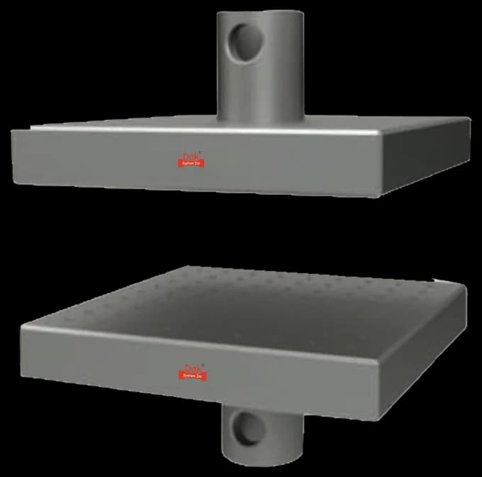
Direct compression platens with a self-aligning upper face, which is what lets a cut foam cube seat evenly despite faces that are never perfectly parallel.
Specifications
Testing standard
Rigid cellular plastics — Determination of compression properties
Written and technically reviewed by Dak System Inc. engineeringLast reviewed
ISO 844 determines the compression properties of rigid cellular plastics. A cube or prism is compressed between plane parallel platens at roughly 10 % relative deformation per minute. Where a maximum force occurs before 10 % deformation, the compressive strength is the stress at that maximum; otherwise the reported value is the compressive stress at 10 % relative deformation.
From the test method to your testing system
Explore the DAK machines already listed for ISO 844, then review the grips, measurement and setup requirements below.
 Universal Testing MachineSeries 7200Explore the machine →
 Universal Testing MachineSeries 9000Explore the machine →
01Understand the method
A cube or prism of rigid cellular plastic, most commonly 50 mm on a side, is stood between two plane parallel compression platens with the upper one free to self-align. A small defined contact load establishes the deformation datum. The platens then close at a rate giving approximately 10 % relative deformation per minute, and force is recorded against deformation. The test runs to the maximum force where one occurs before 10 % deformation, and otherwise to 10 % relative deformation. Which of the two the reported figure came from is part of the result, and the loading direction relative to the foam's rise is recorded throughout.
The method gives compressive stress at maximum force, or compressive stress at 10 % relative deformation, and compressive modulus where a clean linear region exists. These are the properties that decide whether a rigid foam can be used where it carries load — beneath screeds and cold-store floors, in flat-roof build-ups, as the core of a sandwich panel, and in protective packaging designed to absorb energy by crushing. In a sandwich panel it is very often the core's through-thickness compression, rather than the facings, that limits what the panel can take at a fixing or a local load. Because compressive strength tracks density and cell quality closely, the test doubles as a sensitive production control.
02Prepare the specimen and test settings
The cut is the preparation. Rigid foam cannot be machined to a fine finish, so the method is written around what a good blade can achieve and a self-aligning platen can forgive.
Because the fallback value is read at a fixed 10 % relative deformation, anything that shifts the deformation datum — a gap at zero, a wedge-shaped specimen, a compliant load string — moves the reported stress directly.
03Build the test setup on a DAK machine
Force measurement to ISO 7500-1 Class 1 across a working range that may run from a few hundred newtons for light insulation grades to tens of kilonewtons for dense structural foam — accuracy over the range that is actually used, not merely at full scale. The crosshead must hold a slow rate accurately, since 10 % relative deformation per minute on a 50 mm specimen is 5 mm/min. Platens must be plane, parallel and larger than the specimen, with the upper one free to self-align. Because the fallback value is read at a fixed 10 % relative deformation, everything that shifts the deformation datum shifts the reported stress directly: the contact load must be defined, the zero taken at contact rather than at a gap, and frame compliance accounted for on stiffer grades.
Direct compression platens with a self-aligning upper face, which is what lets a cut foam cube seat evenly despite faces that are never perfectly parallel.
SpecificationsDak verifies against whichever standard the method names, and where a class applies our frames sit a class tighter than it asks.
| The method asks for | Dak supplies | |
|---|---|---|
| Capacity | Low to moderate — commonly 0.3 to 5 kN on a 50 mm cube of insulation-grade material | Load cells from 1 kg to 60 ton on the Series 7200, and 0.5 to 100 kN on the Series 9000 |
| Force accuracy | ISO 7500-1 Class 1 over the working range | ISO 7500-1 Class 0.5 — a class tighter than the method asks |
| Gripping | Plane parallel compression platens larger than the specimen, one self-aligning | Our compression anvils, built to the specimen |
| Environment | 23 ± 2 °C and 50 ± 5 % RH | 3009 series chambers, −150 °C to +400 °C — temperature only |
04Run the test
05Calculate, report and interpret
σm = Fm / A₀
εm = Δh / h₀ × 100
Ec = Δσ / Δε over the initial linear region
Requires a clean linear region, which in turn requires faces good enough to seat at once. Where the toe is large the modulus should be reported as indeterminate rather than fitted through it.
Omitting the loading direction is the most consequential error, because rigid foams are anisotropic by a wide margin and a mixed data set looks like process instability. Confusing the two possible outputs is next: a stress at maximum force and a stress at 10 % relative deformation are different quantities, and only one exists for a given specimen. A toe from roughly cut faces both depresses the modulus and shifts the deformation axis, which matters doubly here because the fallback stress is read at a fixed deformation. Leaving facings on an insulation board inflates strength considerably. And running every specimen size at one crosshead speed strains them at different rates, which a rate-sensitive material repays with scatter.
06Compare methods and find answers
| ISO 844 | ASTM D1621 | |
|---|---|---|
| Common specimen | 50 mm cube | Minimum 25.8 cm² area, 25.4–50.8 mm high |
| Rate | About 10 % relative deformation per minute | About 10 % of height per minute |
| Primary result | Stress at maximum force | Compressive strength at yield |
| Fallback | Stress at 10 % relative deformation | Stress at 10 % deformation |
The intent is the same and the rates are equivalent, but the specimen geometries are not identical and rigid foam is geometry-sensitive. Certificates should name the method actually run rather than the family.
It is the ISO method for the compression properties of rigid cellular plastics. A cube or prism is compressed between plane parallel platens at about 10 % relative deformation per minute. Where a maximum force occurs before 10 % deformation, the compressive strength is the stress at that maximum; otherwise the reported figure is the stress at 10 % relative deformation.
Very little in intent and a certain amount in detail. Both deform at roughly 10 % per minute and both fall back to the stress at 10 % deformation where no maximum appears. The specimen geometries differ — ISO 844 commonly uses a 50 mm cube, D1621 specifies a minimum area and a height range — and rigid foam is sensitive enough to geometry that the figures should not be pooled. Run whichever the specification names.
Because rigid foam cells elongate along the direction in which the foam rose, which makes the material substantially stiffer and stronger in that direction than across it — often by a factor of two or more. This is real anisotropy, not scatter. A data set mixing directions looks like an unstable process, and a figure quoted without its direction cannot be used for design.
Then the reported value is the compressive stress at 10 % relative deformation, identified as such. Many rigid foams crush progressively rather than reaching a clear peak. The two outputs are different quantities and must not be mixed within a data set or compared between suppliers without checking which was reported.
Usually because the specimen seated progressively. Foam is cut rather than machined, so a face that is torn or slightly out of parallel makes contact over a range of travel instead of at once, and the resulting toe is soft. If the toe is large enough that no clean linear region exists, the honest answer is to report the modulus as indeterminate rather than fit a slope through a seating artefact.
For a material property to ISO 844, yes — facings and skin are much denser than the core and can carry a large share of the load. Where the board is used with its facings and the question is how the board performs, that is a test on a different article and should be described as such rather than reported as the foam's compressive strength.
It is an inclined band of collapsed cells that forms across the specimen, and yes, for practical purposes it ends the useful part of the curve. Once it forms, further travel is crushing a specimen that has already failed, so the maximum force before or at the band is the meaningful value. Watching for it also helps distinguish genuine material failure from a specimen that was simply loaded off-square.
Discuss your specimen, test requirements and reporting needs with DAK engineering.
This page describes the method as practised. The governing text is the current edition from the issuing body. Tell us what you are testing and we will answer with the machine, the fixture and a quotation.