
Rigidly fixedTJ-146
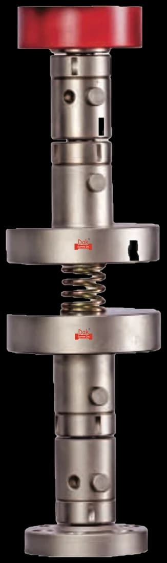
Compression Anvils
Hardened, polished parallel anvils. This method's accuracy rests on their flatness more than on anything the frame does.
Specifications
Testing standard
Plastics — Determination of compressive properties
Written and technically reviewed by Dak System Inc. engineeringLast reviewed
ISO 604 measures the compressive properties of plastics. A small bar stands on end between two hardened polished plates and is squeezed along its axis while force and shortening are recorded. It reports compressive stress at yield, at break and at a nominated strain, the corresponding strains, and compressive modulus taken as the chord between 0.05 % and 0.25 % strain.
From the test method to your testing system
Explore the DAK machines already listed for ISO 604, then review the grips, measurement and setup requirements below.
 Universal Testing MachineSeries 7200Explore the machine →
 Universal Testing MachineSeries 9000Explore the machine →
01Understand the method
A small rectangular bar of plastic stands on end between two hardened, polished steel plates. No grips are involved — the crosshead drives the upper plate down at a constant rate and the specimen is squeezed along its long axis while force and shortening are recorded continuously. Testing runs until the specimen yields, ruptures, or reaches a preset deformation, so the whole compressive stress–strain curve is captured.
The method reports compressive stress at yield, at break and at a nominated strain, the corresponding compressive strains, and compressive modulus taken as the chord between 0.05 % and 0.25 % strain. Modulus feeds stiffness calculations and finite-element models for parts loaded in compression — bearing pads, housings, snap fits under preload. Yield stress sets the load at which a moulded part deforms permanently. Because plastics are rate- and temperature-sensitive, the figures serve material selection and lot release rather than predicting service behaviour at other rates.
02Prepare the specimen and test settings
End preparation is the whole difficulty of this method. Poor ends do not merely add scatter — they put a false toe on the curve, and the toe sits exactly where modulus is measured.
03Build the test setup on a DAK machine
The loaded section is only 10 × 4 mm, so most plastics reach compressive strength below 10 kN and a 5–20 kN frame is ample. Capacity is the easy part. The first modulus point sits at 0.05 % strain, around 50 N on a standard specimen, so fine low-end resolution matters far more than headline capacity. Force must be indicated to ±1 % or better of the relevant value under ISO 5893 — equivalent to ISO 7500-1 Class 1.
Speed is selected from 1, 2, 5, 10 or 20 mm/min, held to ±20 % below 20 mm/min and ±10 % at 20 mm/min. In practice 1 mm/min is used for modulus and for brittle materials, 5 mm/min for ductile ones; rate-sensitive plastics give different numbers at different speeds, so the speed used is reported with the result.
Strain is measured on the specimen, not from crosshead travel. The method sets the requirement directly rather than citing an ISO 9513 class: accuracy of ±1 % or better of the strain interval used, which works out as ±1 µm on a 50 mm gauge length over a 0.2 % interval. Bonded longitudinal strain gauges are accepted at the same accuracy, a strain accuracy of 2.0 × 10⁻⁵. Loading must be axial within 1:1000 through plates flat within 0.025 mm and perpendicular to the loading axis; a self-aligning seat may be fitted where alignment cannot otherwise be held.
Hardened, polished parallel anvils. This method's accuracy rests on their flatness more than on anything the frame does.
Specifications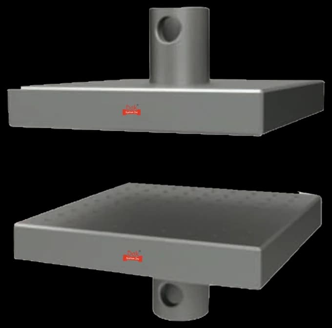
Direct compression platens where the specimen or the supported arrangement needs a larger bearing face.
SpecificationsDak verifies against whichever standard the method names, and where a class applies our frames sit a class tighter than it asks.
| The method asks for | Dak supplies | |
|---|---|---|
| Capacity | The loaded section is only 10 × 4 mm, so most plastics reach compressive strength below 10 kN, while the first modulus point at 0.05 % strain sits around 50 N — the frame needs fine low-end resolution far more than it needs capacity, and 5–20 kN is ample. | Load cells from 1 kg to 60 ton on the Series 7200, and 0.5 to 100 kN on the Series 9000 |
| Force accuracy | ISO 5893 (load indicated to ±1 % or better of the relevant value — equivalent to ISO 7500-1 Class 1) | ISO 7500-1 Class 0.5 — a class tighter than the method asks |
| Strain measurement | An extensometer to no ISO 9513 class is cited — the method sets the requirement directly: accurate to ±1 % or better of the strain interval used, which it works out as ±1 µm for compressive modulus on a 50 mm gauge length over a 0.2 % strain interval. Bonded longitudinal strain gauges are an accepted alternative at the same 1 % accuracy, corresponding to a strain accuracy of 2.0 × 10⁻⁵., gauge length 50 (type A, for compressive modulus — the only gauge length ISO 604 states); no gauge length is defined for the type B or Annex A specimens, where strain is nominal compressive strain taken between the compression-plate contact surfaces | Certified to ISO 9513 Class 1 and ASTM E83 — non-contact video, clip-on and high-elongation |
| Gripping | Hardened, polished parallel compression plates with an optional self-aligning seat; strain taken by clip-on extensometer or bonded strain gauges | Our compression anvils, built to the specimen |
| Environment | Ambient — ISO 291 standard atmosphere 23/50 | 3009 series chambers, −150 °C to +400 °C — temperature only |
04Run the test
A false toe from poor end contact sits precisely over the 0.05 % to 0.25 % interval where modulus is taken. That is why this method spends more of its text on machining the ends than on running the test.
05Calculate, report and interpret
σ = F / A₀
ε = ΔL₀ / L₀
Ec = (σ2 − σ1) / (ε2 − ε1)
The chord across a fixed narrow interval, exactly as ISO 527 does in tension. On a short compression specimen that interval is a very small displacement, which is why end preparation and platen parallelism dominate the result.
Euler buckling is the dominant error: a specimen too slender for its modulus collapses sideways and reports a strength that is a geometry number, not a material one. Barrelling is the opposite case — friction at the plate faces restrains the ends, the mid-section bulges, and stress is no longer uniform. Toe-region curvature from seating and acceleration at the start inflates apparent strain and depresses modulus unless corrected. Machine compliance does the same, since the frame's own deflection is read as specimen shortening; the 2002 edition adds a normative compliance correction for exactly this.
06Compare methods and find answers
| ISO 604 | ASTM D695 | |
|---|---|---|
| Specimen | Machined from an ISO 3167 bar | 12.7 mm square prism or cylinder |
| Height rule | Set by stiffness to avoid buckling | Slenderness ratio 11:1 to 16:1 |
| Modulus | Chord, 0.05 % to 0.25 % strain | Slope of the initial straight portion |
| Speed | Modulus stage plus strength stage | 1.3 mm/min throughout |
As in tension, the modulus definitions are different quantities rather than two attempts at one. A material's ISO compressive modulus and its ASTM one are not interchangeable and cannot be converted between.
It is the international standard for the compressive properties of plastics. A small bar stands on end between two hardened polished plates and is squeezed along its axis, and the method reports compressive stress at yield, at break and at a nominated strain, the corresponding strains, and compressive modulus.
As the chord between 0.05 % and 0.25 % strain — the same fixed interval ISO 527 uses in tension. On a short compression specimen that represents a very small displacement, which is why end preparation and platen parallelism dominate the accuracy of the figure.
Because a specimen that is too slender buckles before it reaches true compressive failure, and the result then describes a column rather than a material. ISO 604 sets the height from the material's stiffness rather than fixing it absolutely, so a stiffer grade tolerates a taller specimen than a soft one.
A sawn end is neither flat nor square enough. The specimen then seats progressively as load is applied, which puts a false toe on the start of the curve — and that toe sits exactly over the 0.05 % to 0.25 % strain interval where modulus is measured. Turning or milling to within 0.025 mm removes it.
The specimen and the modulus definition. ISO 604 machines its specimen from an ISO 3167 multipurpose bar and takes a chord between two fixed strains; D695 uses a 12.7 mm prism proportioned by slenderness ratio and takes the slope of the initial straight portion. The two moduli are different quantities and should not be pooled.
For modulus, effectively yes. The 0.05 % to 0.25 % interval on a short specimen is a displacement small enough that the frame's own compliance is comparable to it, so crosshead travel cannot supply the strain. The strength properties are more forgiving.
Discuss your specimen, test requirements and reporting needs with DAK engineering.
This page describes the method as practised. The governing text is the current edition from the issuing body. Tell us what you are testing and we will answer with the machine, the fixture and a quotation.