
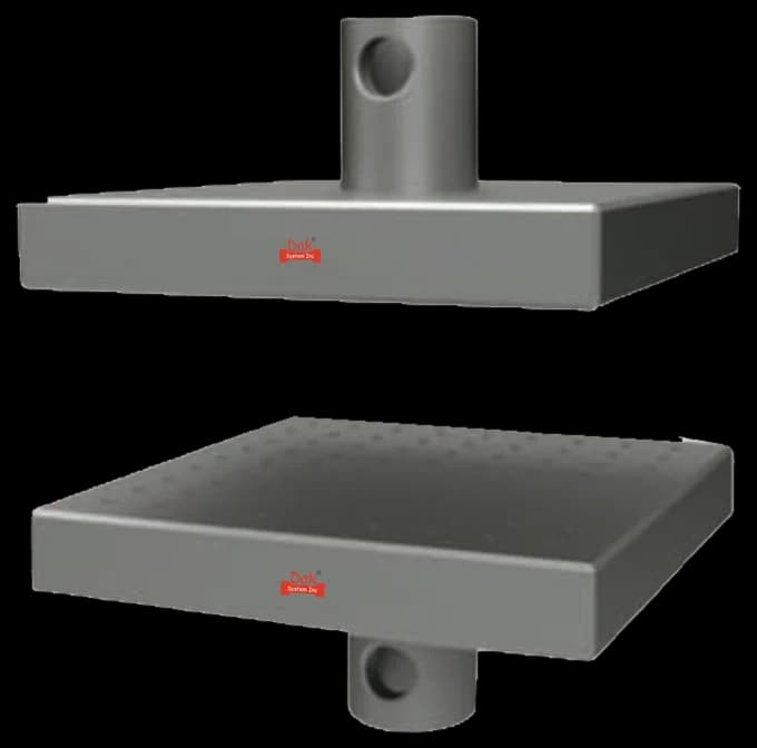
5 to 400 kNTJ-125
Direct Compression Fixture
Flat parallel platens of a hardness and flatness suited to concrete, with a spherically seated upper platen so the load finds the specimen rather than the specimen finding the platen.
Specifications
Testing standard
Standard Test Method for Compressive Strength of Cylindrical Concrete Specimens
Written and technically reviewed by Dak System Inc. engineeringLast reviewed
ASTM C39 determines the compressive strength of cylindrical concrete specimens — moulded cylinders and drilled cores — for concrete with a density above 800 kg/m³. The reported strength is the maximum load over the cross-sectional area, and the fracture pattern is recorded with it.
From the test method to your testing system
Explore the DAK machines already listed for ASTM C39/C39M, then review the grips, measurement and setup requirements below.
 Universal Testing MachineSeries 7200Explore the machine →
 Universal Testing MachineSeries 9000Explore the machine →
01Understand the method
A moulded cylinder or a drilled core of concrete denser than 800 kg/m³ has its diameter measured and its ends checked for planeness and perpendicularity, being capped or ground where they fail. It is centred on the lower bearing block, the spherically seated upper block is brought into contact and allowed to seat itself, and load is applied continuously and without shock at a stress rate on the specimen of 0.25 ± 0.05 MPa/s (35 ± 7 psi/s), without easing off as failure approaches. That rate has to be held through at least the second half of the anticipated loading phase; a faster rate is permitted through the first half, and no adjustment is made once the specimen has begun to yield. On the 150 by 300 mm cylinder the section is 17 670 mm², so 0.25 MPa/s is a force rate of 4.4 kN/s and the permitted band is 3.5 to 5.3 kN/s — a 40 MPa concrete reaching 707 kN therefore takes roughly two and a half minutes. On the 100 by 200 mm cylinder the same stress rate is 2.0 kN/s. The maximum load divided by the measured average area gives the compressive strength, and the fracture pattern is identified against the types the method illustrates.
The strength of the concrete as placed — the number a structure is designed around and accepted on. The most useful thing to understand about it is that the specimen shape is part of the answer. Friction between platen and specimen restrains the ends from spreading, putting them into triaxial compression, which is a stronger state than uniaxial. That restraint reaches a fixed distance into the specimen, so it dominates a squat cube and largely spares the mid-height of a slender cylinder. A cube and a cylinder of identical concrete therefore give different strengths, and the difference is geometry rather than material.
02Prepare the specimen and test settings
A cylinder and a cube of the same concrete do not give the same strength. Platen restraint is the reason.
Platen friction restrains the ends of the specimen and puts them into triaxial compression, which raises the measured strength. That restraint reaches further into a short specimen than a slender one, which is why a cube reads higher than a cylinder of the same concrete.
03Build the test setup on a DAK machine
Very high force and a well-made load train. A 150 by 300 mm cylinder at 60 MPa needs above a thousand kilonewtons and higher grades go further, so this is a dedicated compression frame rather than a general-purpose one. The upper bearing block must be spherically seated and must actually move — a seized seat behaves as a rigid platen while still being called a spherical one, and it will not announce itself. Bearing blocks need the specified hardness and flatness, and the frame enough stiffness to absorb an abrupt failure.
Flat parallel platens of a hardness and flatness suited to concrete, with a spherically seated upper platen so the load finds the specimen rather than the specimen finding the platen.
SpecificationsDak verifies against whichever standard the method names, and where a class applies our frames sit a class tighter than it asks.
| The method asks for | Dak supplies | |
|---|---|---|
| Capacity | Very high — a 150 x 300 mm cylinder at 60 MPa needs above 1000 kN | Load cells from 1 kg to 60 ton on the Series 7200, and 0.5 to 100 kN on the Series 9000 |
| Force accuracy | ASTM E4 over the working range | Verified to ASTM E4, and to ISO 7500-1 Class 0.5 |
| Gripping | A compression frame with a spherically seated upper platen and bearing blocks to the specified flatness | Our compression anvils, built to the specimen |
| Environment | 23 ± 2 °C standard laboratory atmosphere | 3009 series chambers, −150 °C to +400 °C — temperature only |
04Run the test
05Calculate, report and interpret
Maximum load divided by the average cross-sectional area
Measured, not nominal. A mould wears and a core is rarely exactly its nominal diameter.
Platen restraint reaches further into a squat specimen than a slender one
A 150 mm cube and a 150 x 300 mm cylinder of identical concrete give different numbers. Converting between them is a convention, not a measurement, and the specification says which shape it means.
Applied where the length-to-diameter ratio is below the standard value
A short core is more restrained and reads high, so the raw figure needs correcting before it is comparable.
Loading faster than specified, or easing off as failure approaches; concrete is rate-sensitive and both bias the answer, in opposite directions. Untested spherical seats. Ends left unprepared. Calculating on a nominal diameter when moulds wear and cores are rarely exactly nominal. And the one that travels furthest: comparing a cube result with a cylinder result as though they measured the same thing, when the conversion between them is a convention rather than a measurement. Skipping the core correction sits alongside it: a short core is more restrained than a full-height cylinder and reads high, so an uncorrected figure flatters the concrete it came from, and the flattery grows as the core gets shorter.
06Compare methods and find answers
| ASTM C39 | IS 516 (Part 1/Sec 1) | |
|---|---|---|
| Specimen | 150 x 300 mm cylinder, or a core | 150 mm cube |
| Restraint | Less — the mid-height is far from the platens | More — the platens are closer together |
| Reads | Lower for the same concrete | Higher for the same concrete |
| Interchangeable | No — the specification states which shape it means | No |
The single most useful thing to know about concrete strength testing: a cube and a cylinder of the same mix give different numbers, and the difference is geometry rather than material. Never compare across shapes without saying so.
It is the ASTM test for the compressive strength of cylindrical concrete specimens, covering both moulded cylinders and drilled cores. It applies to concrete with a density above 800 kg/m³. The specimen is crushed between bearing blocks at a specified stress rate and the maximum load divided by the measured area gives the strength.
Because of platen restraint. Friction between the bearing block and the specimen stops the ends spreading sideways, putting them into triaxial compression, which is a stronger state than uniaxial. That restraint reaches a fixed distance into the specimen, so in a squat cube it influences most of the height while in a slender cylinder the mid-height escapes it. The difference is geometry, not concrete, and it is why a specification always states which shape it means.
So the block can rotate a little and meet the specimen's end squarely. Concrete ends are rarely perfectly plane and perpendicular, and a rigid platen would bear on whichever point is proudest, concentrating the load and splitting the cylinder from there. The seat lets contact spread over the whole face. If it has seized — which happens, and quietly — the machine has a rigid platen wearing the right name.
Because an unusual one is a warning. The method illustrates the expected types — cone, cone-and-split, cone-and-shear, shear and columnar — and a fracture that does not resemble any of them usually points at a badly prepared end, a seized spherical seat, or a specimen that was not what it should have been. The strength on its own cannot tell you that; the fracture can.
Yes, and that is why the rate is fixed at 0.25 ± 0.05 MPa/s (35 ± 7 psi/s) rather than left to the operator. Concrete is rate-sensitive: load it faster and it reads stronger. The temptation is to slow down or ease off as failure approaches, which biases the result the other way. The rate has to hold through at least the second half of the anticipated loading phase precisely because that is where the error would enter — a higher rate is allowed through the first half, and once the specimen starts yielding rapidly the platen movement is left alone. On a 150 by 300 mm cylinder that stress rate is a force rate of 4.4 kN/s.
Because a drilled core is often shorter relative to its diameter than a moulded cylinder, and a squatter specimen is more restrained by the platens and therefore reads high. Recording the length-to-diameter ratio and applying the correction where it falls below the standard value is what makes a core result comparable with a cylinder one.
More than most laboratory frames. A 150 by 300 mm cylinder at 60 MPa needs above a thousand kilonewtons, and higher-grade concretes go further. The frame also needs bearing blocks of the specified hardness and flatness, and enough stiffness that the sudden release at failure does not damage it — concrete fails abruptly and completely.
Discuss your specimen, test requirements and reporting needs with DAK engineering.
This page describes the method as practised. The governing text is the current edition from the issuing body. Tell us what you are testing and we will answer with the machine, the fixture and a quotation.