Testing standard

ASTM D2412

Standard Test Method for Determination of External Loading Characteristics of Plastic Pipe by Parallel-Plate Loading

Written and technically reviewed by Dak System Inc. engineeringLast reviewed

ASTM D2412 measures how a plastic pipe resists being squashed. A ring of pipe is laid on its side between two flat parallel plates and compressed at 12.5 mm/min. Load and vertical deflection give pipe stiffness and stiffness factor, normally reported at 5 % deflection of the inside diameter, along with any cracking or wall buckling seen along the way.

At a glance

Test type
Compressionthe specimen is squeezed
Published by
ASTM
Edition
D2412-21

What the test does

A ring cut from the pipe, at least 150 mm long, is laid on its side on a flat steel plate. A second flat plate, parallel to the first and long enough to overhang the specimen at both ends, is brought down onto it at 12.5 ± 0.5 mm/min. The ring is squashed vertically and force is recorded against the reduction in vertical diameter. The inside diameter is measured before loading, because every reported deflection is expressed as a percentage of it. The load at 5 % deflection is the usual reporting point, and the test frequently continues well beyond it to look for cracking, wall buckling or layer separation.

What it measures, and why it matters

The primary outputs are pipe stiffness and stiffness factor. Pipe stiffness is what a designer needs when a buried pipe has to survive the weight of soil and traffic above it: a flexible pipe carries external load partly through its own ring stiffness and partly by deflecting into the surrounding soil, and the balance between the two decides the installation. Stiffness factor converts the measurement into a quantity proportional to the wall's bending stiffness, which — unlike pipe stiffness — can be compared between diameters and wall constructions. For structured-wall, ribbed and multi-layer pipe the test is also the practical way to verify that a complicated wall behaves as designed, since no simple calculation captures it.

Specimen and plates

The specimen is a slice of the product rather than a machined coupon, so it carries the pipe's real wall structure — including any ribs, layers or foam core.

Specimen length
150 mm minimum, or as the product requiresLong enough to be representative of the wall, and for profiled or ribbed pipe long enough to include whole profile repeats.
Cut ends
Square and smoothA ragged end concentrates stress and starts a crack that has nothing to do with the wall design.
Plates
Flat, parallel, and longer than the specimenThey must overhang both ends, or the pipe ends carry a line load.
Plate stiffness
Enough not to bow under the test loadA bowing plate unloads the middle of the specimen and reads soft. This is the commonest apparatus fault in the test.
Measure the inside diameter
Before loadingEvery reported deflection is a percentage of it, so an assumed nominal diameter puts a systematic error into every result.
Mark the orientation
And keep it consistentDakExtruded pipe is rarely perfectly round or uniform in wall thickness; loading the same orientation across a set removes a real source of scatter.

Pipe stiffness is a property of the pipe, not of the plastic. It combines material modulus with wall geometry, so it cannot be transferred between diameters or wall constructions.

Test speed

Plate speed
12.5 ± 0.5 mm/min
Usual reporting point
5 % deflection of the inside diameterOther percentages are commonly specified as well, and the reporting points belong with the figures.
Continue past the reporting point
Where the specification asksMany product specifications require the test to continue to 10 %, 15 % or beyond, looking for cracking, wall buckling or delamination rather than for a number.
Note the deflection at which anything visible happens
Cracking, buckling, layer separationDakThese observations are often the actual acceptance criterion, and a load-deflection curve alone will not show them.

Calculations

Pipe stiffnessPS

PS = F / Δy

F
force per unit length of specimen, N/mm
Δy
vertical deflection, mm

Force per unit length, so the specimen length divides out and specimens of different lengths are comparable.

Stiffness factorSF

SF = 0.149 r³ × PS

r
mean radius of the pipe, mm
PS
pipe stiffness, N/mm per mm

Recovers a quantity proportional to the wall's bending stiffness, EI, which unlike pipe stiffness can be compared across diameters.

How the test runs

  1. 01Cut ring specimens at least 150 mm long with square, smooth ends.
  2. 02Measure the inside diameter and wall thickness, and record them.
  3. 03Condition at 23 ± 2 °C.
  4. 04Check the plates are flat, parallel and longer than the specimen.
  5. 05Lay the ring on the lower plate in the recorded orientation.
  6. 06Close to light contact and zero force and deflection.
  7. 07Compress at 12.5 mm/min, recording force against plate separation.
  8. 08Record the load at 5 % deflection of the inside diameter.
  9. 09Continue to any further deflections the specification names.
  10. 10Note the deflection at which cracking, buckling or delamination first appears.
  11. 11Calculate pipe stiffness and stiffness factor.

The fixture this method needs

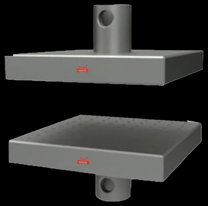
Direct compression fixture platens
5 to 400 kNTJ-125

Direct Compression Fixture

Direct compression platens carrying flat parallel plates. What the method demands is that the plates overhang the specimen at both ends and stay flat under load — a plate that bows unloads the middle of the ring and the pipe reads soft.

Specifications

What the report has to contain

  • Reference to ASTM D2412 and the edition
  • Pipe identification, material and wall construction
  • Nominal size, measured inside diameter and wall thickness
  • Specimen length and number tested
  • Conditioning temperature
  • Plate speed
  • Load and deflection at each specified percentage
  • Pipe stiffness and stiffness factor
  • The deflection at which cracking, buckling or delamination occurred, if any
  • Specimen orientation relative to any marking or seam

What the machine must be capable of

Force measurement to ASTM E4 over a very wide range — a thin-wall small-diameter pipe may reach 5 % deflection under a few hundred newtons, while heavy-wall sections need tens of kilonewtons — and a crosshead holding 12.5 mm/min. The demanding part is the plates rather than the frame: they must be flat, parallel, longer than the specimen at both ends, and stiff enough not to bow under the test load. Plate bowing is the commonest apparatus fault in this test and it biases results low, because a flexing plate unloads the middle of the specimen relative to its ends. The frame also needs enough daylight and platen width to take the pipe diameters being tested.

What goes wrong in practice

Two systematic errors dominate, and both bias in one direction rather than adding scatter. Plates that bow under load unload the centre of the specimen and make every pipe read soft. Using a nominal rather than a measured inside diameter shifts every deflection percentage, and therefore every reported load. Beyond those, the frequent reporting mistake is treating a D2412 pipe stiffness figure and an ISO 9969 SN rating as interchangeable; they are different quantities, at different reference deflections, with different formulae. Finally, on structured-wall pipe a specimen that does not contain whole profile repeats is not representative of the wall, and no amount of care elsewhere recovers that.

ASTM D2412 or ISO 9969

ASTM D2412ISO 9969
OutputPipe stiffness PS and stiffness factor SFRing stiffness S, in kN/m²
Reference diameterInside diameterInside diameter
Usual reporting deflection5 % of inside diameter3 % of inside diameter
FormulaPS = F/Δy; SF = 0.149 r³ PSS includes a deflection-dependent correction term

These give different numbers with different units and different reporting deflections, and neither converts cleanly into the other. A pipe specified as SN8 to ISO 9969 has not been shown to meet a D2412 pipe stiffness requirement, or the reverse.

Questions we are asked about this test

What is ASTM D2412?

It is the ASTM test method for the external loading characteristics of plastic pipe by parallel-plate loading. A ring of pipe is laid on its side between two flat parallel plates and compressed at 12.5 mm/min. The result is pipe stiffness and stiffness factor, normally quoted at 5 % deflection of the inside diameter, together with observations of any cracking or buckling.

What is the difference between pipe stiffness and stiffness factor?

Pipe stiffness, PS, is force per unit length divided by deflection — a direct measure of how much this pipe resists being squashed. Stiffness factor, SF, multiplies it by 0.149 r³ to recover a quantity proportional to the wall's bending stiffness. PS describes the article and cannot be transferred between diameters; SF describes the wall and can.

Can I compare a D2412 result with an ISO 9969 SN rating?

Not directly. They report different quantities in different units and at different reference deflections — D2412 at 5 % of the inside diameter, ISO 9969 at 3 % — and ISO 9969's formula carries a deflection-dependent correction that D2412 does not. A pipe qualified as SN8 has not thereby been shown to meet a D2412 requirement, or the reverse. Where both are required, both are run.

Why do my results come out low?

The most frequent apparatus cause is plates that bow under load. If the plates flex, the middle of the specimen is unloaded relative to its ends and the pipe reads softer than it is. The next most frequent is using a nominal inside diameter rather than a measured one, since every deflection is a percentage of that dimension. Both produce a consistent bias rather than scatter, which makes them easy to overlook.

Does the test destroy the pipe?

Not necessarily. At 5 % deflection most pipes are still within their elastic response and recover. Where the specification calls for the test to continue to 10 %, 15 % or further, it is usually looking for cracking, wall buckling or layer separation — and there the observation, not the load, is the acceptance criterion. Recording the deflection at which anything visible first happens is part of the result.

How long should the specimen be?

At least 150 mm, and longer where the wall is profiled. Structured-wall and ribbed pipes have a repeating profile, and a specimen that cuts through the middle of a rib rather than including whole repeats does not represent the wall. For those products the specimen length is chosen around the profile pitch rather than a flat minimum.

Why does specimen orientation matter?

Because extruded pipe is rarely perfectly round and its wall thickness is rarely perfectly uniform. Loading a thin part of the wall at the crown gives a different answer from loading a thick part there. Marking the orientation and keeping it consistent across a set does not make the pipe uniform, but it does stop that non-uniformity appearing as random scatter.


Running ASTM D2412 on the Series 7200 and Series 9000

Dak verifies against whichever standard the method names, and where a class applies our frames sit a class tighter than it asks.

The method asks forDak supplies
CapacityWide — from a few hundred newtons on thin-wall small-diameter pipe to tens of kilonewtons on heavy-wall sectionsLoad cells from 1 kg to 60 ton on the Series 7200, and 0.5 to 100 kN on the Series 9000
Force accuracyASTM E4Verified to ASTM E4, and to ISO 7500-1 Class 0.5
GrippingTwo flat parallel steel plates, longer than the specimen and stiff enough not to bow under loadOur compression anvils, built to the specimen
Environment23 ± 2 °C; temperature matters because pipe stiffness is temperature-dependent3009 series chambers, −150 °C to +400 °C — temperature only

This page describes the method as practised. The governing text is the current edition from the issuing body. Tell us what you are testing and we will answer with the machine, the fixture and a quotation.

Materials tested to it

The test it standardises

Other standards explained