
Rigidly fixedTJ-146
Compression Anvils
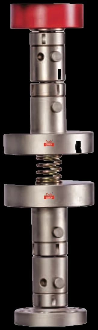
Hardened parallel anvils. Flatness and parallelism here are part of the method rather than a property of the machine — an anvil out of true loads a corner first and depresses modulus.
Specifications
Testing standard
Standard Test Method for Compressive Properties of Rigid Plastics
Written and technically reviewed by Dak System Inc. engineeringLast reviewed
ASTM D695 measures how rigid plastics behave in compression. A short prism or cylinder stands unclamped between two flat platens and is squeezed along its axis at a slow constant speed. It reports compressive strength, compressive yield and offset yield, modulus from the initial straight portion of the curve, and deformation at a stated load.
From the test method to your testing system
Explore the DAK machines already listed for ASTM D695, then review the grips, measurement and setup requirements below.
 Universal Testing MachineSeries 7200Explore the machine →
 Universal Testing MachineSeries 9000Explore the machine →
01Understand the method
A short prism or cylinder of rigid plastic is stood on a flat hardened platen, unclamped and unbonded. The crosshead drives a second platen down onto its opposite face at a constant slow speed, squeezing the specimen along its long axis. Force and shortening are recorded continuously until the specimen fractures, flattens completely, or reaches a preset load or reduction in length.
The method reports compressive strength, compressive yield and offset yield, modulus of elasticity from the straight initial portion of the curve, and deformation at a stated load. Compressive strength governs housings, bushes, standoffs and any moulding that carries a bearing load, and it is the figure a designer needs when tensile data alone would be misleading. Modulus feeds stiffness and buckling calculations directly. Strength at a fixed offset is the usual lot-release criterion for structural mouldings, since it is repeatable where ultimate strength of a ductile grade is not.
02Prepare the specimen and test settings
Everything about this specimen exists to make it crush rather than buckle. Get the proportions wrong and the number describes a column, not a material.
03Build the test setup on a DAK machine
Unreinforced rigid plastics on the standard 12.7 mm square section usually fail between roughly 1 and 20 kN, while reinforced and highly orthotropic laminates on the same section can run past 50 kN, so a 50–100 kN frame covers the range. Force indication must be verified to ASTM E4. Speed is fixed at 1.3 ± 0.3 mm/min; after the yield point it may be raised to 5–6 mm/min for relatively ductile materials, and only where the weighing system responds fast enough to follow the load drop. Modulus and offset yield need a compressometer classified to ASTM E83 Class B-2 or better, reading shortening between two fixed points — crosshead travel includes frame and platen compliance, so it flatters the modulus badly. The load must be applied axially within 1:1000 through a compression tool of the subpress type; without that alignment the prism loads one edge first and the recorded strength drops. Specimens under 3.2 mm thick need the bolt-on supporting jig, its screws finger-tight only, with the compressometer clipped to the specimen edges. The compression tool may be dispensed with for low-modulus material, roughly 700 to 3500 MPa, provided the platen faces stay smooth, flat and parallel. Ambient laboratory conditions apply.
Hardened parallel anvils. Flatness and parallelism here are part of the method rather than a property of the machine — an anvil out of true loads a corner first and depresses modulus.
Specifications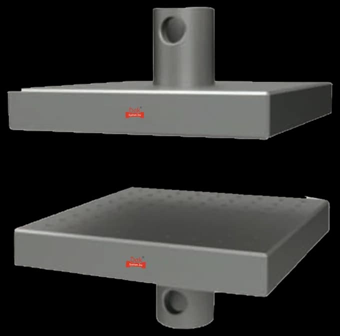
Direct compression platens for larger specimens and for the supported-jig arrangement thin material requires.
SpecificationsDak verifies against whichever standard the method names, and where a class applies our frames sit a class tighter than it asks.
| The method asks for | Dak supplies | |
|---|---|---|
| Capacity | Most unreinforced rigid plastics fail somewhere between about 1 and 20 kN on the standard 12.7 mm square prism, while reinforced and highly orthotropic laminates on the same section can run past 50 kN, so a 50–100 kN frame is the usual choice. | Load cells from 1 kg to 60 ton on the Series 7200, and 0.5 to 100 kN on the Series 9000 |
| Force accuracy | ASTM E4 | Verified to ASTM E4, and to ISO 7500-1 Class 0.5 |
| Strain measurement | An extensometer to ASTM E83 Class B-2, gauge length not specified — the method fixes specimen slenderness ratio (11:1 to 16:1) rather than an extensometer gauge length; the preferred modulus specimen is 50.8 mm long | Certified to ASTM E83 and ISO 9513 Class 1 — non-contact video, clip-on and high-elongation |
| Gripping | Flat hardened compression platens or a compression tool (subpress), plus a bolt-on support jig for specimens thinner than 3.2 mm | Our compression anvils, built to the specimen |
| Environment | Ambient laboratory conditions — 23 °C and 50 % RH per D618 Procedure A, tested at the conditioning conditions | 3009 series chambers, −150 °C to +400 °C — temperature only |
Related resource: Rigid resin testing in construction-chemical laboratories.
04Run the test
05Calculate, report and interpret
σc = P / A₀
Original area throughout. The specimen barrels outward under load and none of that widening enters the calculation.
εc = ΔL / L₀
E = Δσ / Δε over the initial straight portion
Taken from the straight part of the curve. Any toe from imperfect end contact must be corrected out first, or the modulus reads low.
Euler buckling is the headline failure: a specimen machined too long for its section bows and fails at a fraction of its true strength, and the curve looks plausible. End crushing is the opposite error — the loaded faces mushroom into the platens and the recorded stress is diluted by a shortening that is not uniform. Off-axis loading from an unaligned tool loads one corner first and depresses strength. Laminates delaminate under end load rather than crushing, so the number describes the interface, not the material.
06Compare methods and find answers
| ASTM D695 | ISO 604 | |
|---|---|---|
| Standard specimen | 12.7 mm square prism, 11:1 to 16:1 | Prism machined from an ISO 3167 bar, 10 × 4 mm section |
| Modulus | Slope of the initial straight portion | Chord between 0.05 % and 0.25 % strain |
| Speed | 1.3 mm/min | Set by the strain-rate requirement |
| Thin material | Supporting jig below 3.2 mm | Height set by stiffness to avoid buckling |
The modulus definitions differ in the same way the tensile pair does — a slope taken where the curve happens to be straight is not the same as a chord across two fixed strains. Results should not be pooled.
It is the ASTM test method for the compressive properties of rigid plastics. A short prism or cylinder is squeezed between two flat platens at a slow constant speed, and the method reports compressive strength, compressive yield and offset yield, modulus of elasticity and deformation at a stated load.
A right prism or cylinder, most commonly of 12.7 mm square section, proportioned so its slenderness ratio falls between 11:1 and 16:1. That band is what keeps the specimen crushing rather than buckling. The preferred modulus specimen is 50.8 mm long, and material thinner than 3.2 mm needs the bolt-on supporting jig.
1.3 mm/min for the standard specimen — slow compared with a tensile test, because a compression specimen develops load very quickly once the platens are in contact. The test ends at fracture, at complete flattening, or at a preset load or reduction in length.
The slenderness ratio is too high — the specimen is too long for its section, so it behaves as a column and fails by instability rather than by compression. The 11:1 to 16:1 band exists precisely to prevent this, and a buckled specimen produces a number that describes the geometry, not the plastic.
It is the stress at a specified offset from the elastic line, and it is the usual lot-release criterion for structural mouldings. Ductile grades never fracture in compression — they simply flatten — so no ultimate strength exists for them. Offset yield is repeatable where an ultimate figure is not.
Usually a toe on the curve from imperfect end contact. If the ends are not flat within 0.025 mm and square to the axis, the specimen seats progressively rather than all at once, and that early softness is included in the slope. Correcting the toe before taking the modulus, and rejecting out-of-square specimens before loading, removes most of it.
Chiefly the specimen and the modulus definition. ISO 604 machines its specimen from an ISO 3167 multipurpose bar and takes modulus as a chord between 0.05 % and 0.25 % strain; D695 uses a 12.7 mm prism and takes the slope of the initial straight portion. As with the tensile pair, those are different quantities and the results should not be pooled.
Discuss your specimen, test requirements and reporting needs with DAK engineering.
This page describes the method as practised. The governing text is the current edition from the issuing body. Tell us what you are testing and we will answer with the machine, the fixture and a quotation.