Testing standard

ASTM D3167

Standard Test Method for Floating Roller Peel Resistance of Adhesives

Written and technically reviewed by Dak System Inc. engineeringLast reviewed

ASTM D3167 measures the peel resistance of a bond between one rigid and one flexible adherend. The rigid member runs through a cradle of unloaded rollers while the flexible one is pulled away, so the peel angle stays constant as the front advances. The strip is peeled at a constant head speed of 152 mm/min, and the result is the running force divided by the bonded width. The method states that both adherend thicknesses change the value and must be specified.

At a glance

Test type
Peel & adhesiona bonded joint is pulled apart
Published by
ASTM
Edition
D3167-10(2025)

What the test does

Two adherends are bonded along their length, one rigid and one flexible. The rigid member is drawn through a cradle of rollers while the free end of the flexible member is pulled upwards in the opposite grip, so the flexible adherend bends around a small roller and strips off the bond. The rollers turn freely, carrying the rigid adherend along as the peel front advances, so the angle at which the flexible member leaves the bond stays constant all the way down the specimen. Force is recorded continuously against travel, and the running force divided by the bonded width is the result.

What it measures, and why it matters

Peel resistance, expressed as force per unit width. Peel destroys bonded assemblies that were perfectly adequate in shear, because it concentrates the whole load on a moving line rather than spreading it over an area: a structural adhesive carrying tens of megapascals in a lap joint can be walked apart by hand at the edge. The method puts a reproducible number on that. It is used to rank adhesives and primers, to qualify surface preparation, and as a production check where a drifting peel figure is the first sign that a pre-treatment line has changed.

The standard is explicit that the thicknesses of both adherends change the value materially, and that they must therefore be stated in the material requirements. A peel figure quoted without the adherend build is not a comparable number at all. Where no thickness is specified, the method falls back to a flexible adherend of 0.63 mm and a rigid adherend of 1.63 mm.

The bonded strip

One rigid adherend, one flexible adherend, bonded along their length.

Configuration
Flexible adherend bonded to a rigid one
Width
Bonded panels cut into 12.7 mm (0.5 in.) stripsOther widths are permitted where the grip and the peel fixture are wide enough to apply the load uniformly across the adherends. The result is force per unit width either way, so the bonded width is measured and reported.
Default adherends
Clad aluminium alloy 2024-T3, unless otherwise specified
Number of specimens
Two from each of three bonded panels, for every temperature tested
Default flexible adherend thickness
0.63 mmApplies only where the material requirement does not state one.
Default rigid adherend thickness
1.63 mmAs above — a default, not a specification.
Adherend thickness
Materially affects the result; must be specifiedThe method says so in its own scope. A peel figure quoted without the adherend build is not comparable to another one.
Bonded length
Long enough for a substantial run of steady peel
Units
SI are standard; inch-pound values are for reference only
Cut edges
Clean and squareDakA nick at the edge starts a tear that runs ahead of the peel front and reads as low peel resistance.

The flexible adherend has to bend around the roller without yielding or cracking. If it yields, the number describes the adherend and not the adhesive.

Test speed

Head speed
152 mm/min (6 in./min), constantHere the bond separates at the same 152 mm/min, unlike a T-peel, where the bond opens at half the head speed. Some published summaries give 254 mm/min for this method; the published text of the method itself gives 152 mm/min, and that is the figure used here.
Why it is fixed
Peel is rate-sensitiveA machine that surges through a stick-slip event records the surge, so the rate must be held under a fluctuating load.
Reported region
At least 76.2 mm (3 in.) of bond line, after discarding the first 25.4 mm (1 in.) of peelThe initial spike is the peel front getting started, not the resistance of the bond.
Machine requirement
To Practices E4, autographic, with self-aligning gripsThe breaking load should fall between 15 % and 85 % of full-scale capacity, which is why the cell is sized for the specimen and not for the frame.

Calculations

Peel resistanceP

P = F_avg / w

F_avg
average force over the steady peel region, N
w
bonded width, mm

Force per unit width, not a stress. There is no area in the denominator because peel loads a line, not a plane — which is exactly why a bond that is strong in shear can be weak here.

How the test runs

  1. 01Prepare both adherends with the specified surface treatment.
  2. 02Bond them, controlling bond-line thickness, and cure to the adhesive's schedule.
  3. 03Cut the assembly to width with clean, square edges.
  4. 04Measure the bonded width on each specimen.
  5. 05Condition as the adhesive maker specifies, and record what was done.
  6. 06Load the rigid adherend into the floating roller cradle.
  7. 07Clamp the free end of the flexible adherend in the opposing grip.
  8. 08Peel at a constant head speed of 152 mm/min, recording force against travel throughout.
  9. 09Discard the first 25.4 mm of peel and average the force over at least 76.2 mm of bond line.
  10. 10Divide by the measured width, and classify the failure surface.

The fixture this method needs

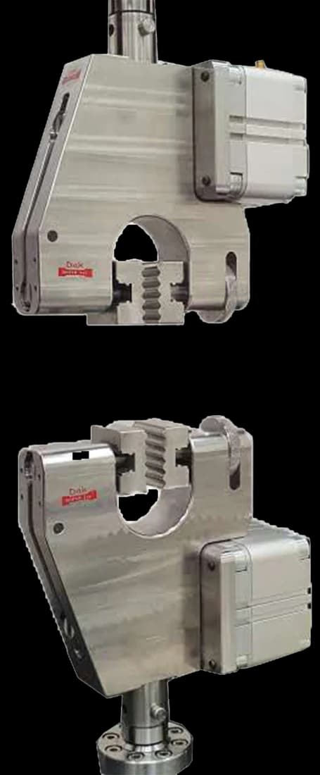
Pneumatic vice action grips with 25 mm square jaw faces
Standard 25 mm

Pneumatic Vice Action Grip

Flat vice-action faces hold the thin flexible adherend across its full width at a constant, gentle pressure. The arm is the specimen here, so a jaw that bites or marks it moves the result. The floating roller cradle itself is made to the method.

Specifications

What the report has to contain

  • Reference to ASTM D3167 and the edition
  • Adhesive identification, batch and cure schedule
  • Both adherend materials and their thicknesses
  • Surface preparation for each adherend
  • Measured bonded width
  • Bond-line thickness where controlled
  • Conditioning procedure and test temperature
  • Head speed used and how the average load was determined
  • Average peel resistance, in force per unit width
  • Whether the trace was steady or stick-slip
  • Failure mode for each specimen
  • Number of specimens, mean and scatter

What the machine must be capable of

Low forces, generous stroke, steady rate. A 12.7 mm strip peels at anywhere from a few newtons for a light laminating adhesive to a couple of hundred for a toughened structural film, so a load cell in the 100 N to 1 kN class resolves the trace; one sized for the frame instead of the specimen buries a soft peel curve in noise. The method asks for a frame to Practices E4, self-aligning grips, a continuous record of load against separation, and a constant head speed of 152 mm/min (6 in./min) — at which the bond separates at that same rate, unlike a T-peel, where it opens at half the head speed. Holding the rate under a fluctuating load matters, because peel is rate-sensitive and a machine that surges through a stick-slip event records the surge. Stroke, not capacity, is the practical constraint: the average is read over at least 76.2 mm (3 in.) of bond line once the first 25.4 mm (1 in.) has been discarded. No extensometer is involved: this is force per unit width, not strain.

What goes wrong in practice

Yielding of the flexible adherend, which turns a peel test into a bend test and gives a number governed by the metal rather than the adhesive. Stick-slip peel, whose saw-toothed trace has peaks that are not the peel resistance; average the running region and say that the trace was unstable. Reading the initial spike as the result, when the method says to discard the first 25.4 mm of peel before averaging. Quoting a value without the adherend thicknesses, which the method itself warns against. And loading the specimen crookedly, so the peel front runs diagonally and the effective width is not the width you measured.

Choosing a peel geometry

ASTM D3167ASTM D1781ASTM D903ASTM D1876
GeometryFloating rollerClimbing drum180° stripT-peel
AdherendsOne rigid, one flexibleFacing off a core or panelOne rigid, one flexibleBoth flexible
Peel angleHeld by the roller cradleHeld by the drum180°, if the fixture keeps it thereSet by the two arms
SeverityGreater than D1781Less severeDepends on the flexible memberDepends on both arms

D3167 names itself an alternative to D1781 and the more severe of the two, because its peel angle is greater. Two peel numbers from different geometries are not interchangeable and should never be compared directly.

Questions we are asked about this test

What is ASTM D3167?

It is the ASTM floating roller peel test for adhesives, used where one adherend is rigid and the other flexible. The rigid member passes through a cradle of unloaded rollers while the flexible one is pulled away, so the peel angle stays constant as the front travels. The result is the average running force divided by the bonded width.

Why is the roller described as floating?

Because the cradle is not clamped in place. It carries the rigid adherend and is free to move as the peel front advances, which is what keeps the angle at which the flexible member leaves the bond constant from one end of the specimen to the other. A fixed arrangement lets the angle drift, and the recorded force drifts with it.

When do I use D3167 rather than D1781?

The method names itself an alternative to D1781, the climbing drum peel test, and says it is the more severe of the two because the peel angle is greater. D1781 suits a facing peeled from a sandwich panel or honeycomb core; D3167 suits a flexible sheet bonded to a rigid one. Results from the two are not interchangeable.

Why does the standard insist on stating adherend thickness?

Because the thickness of both adherends changes the measured value materially, and the method says so in its own scope. A thicker flexible member resists bending and raises the recorded force without the adhesive having changed at all. A peel figure quoted without the adherend build cannot be compared with another laboratory's.

What are the default adherend thicknesses?

Where the material requirement does not specify them, the method falls back to a flexible adherend of 0.63 mm (0.025 in.) and a rigid adherend of 1.63 mm (0.064 in.). Those are defaults for the case where nothing has been agreed, not a specification to be applied over one that has. The default adherend material, again where nothing else is specified, is clad aluminium alloy 2024-T3.

Why is the initial peak excluded?

Because it reflects the energy needed to start separation at one point, not the resistance of the bond to being peeled. The method is specific about it: discard the first 25.4 mm (1 in.) of peel, then average the load over at least the next 76.2 mm (3 in.) of bond line. The reproducible quantity is the steady running force once the front is advancing.

What does a saw-toothed trace mean?

Stick-slip peel: the crack front arrests, load builds, and the front runs forward again. The peaks are not the peel resistance and must not be reported as such. Average the running region and state in the report that the trace was unstable, because that behaviour is itself a finding about the adhesive.

What machine capacity does this test need?

A small one. A 12.7 mm strip peels at a few newtons for a light laminating adhesive and at a couple of hundred for a toughened structural film, so a load cell in the 100 N to 1 kN class is right — the method wants the breaking load between 15 % and 85 % of full scale. Stroke matters more than force: the fixture takes up travel, and better than 100 mm of peel has to be recorded after that.


Running ASTM D3167 on the Series 7200 and Series 9000

Dak verifies against whichever standard the method names, and where a class applies our frames sit a class tighter than it asks.

The method asks forDak supplies
CapacityA 12.7 mm strip peels at a few newtons for a light laminating adhesive and at a couple of hundred for a toughened structural film, so a 100 N to 1 kN load cell suits almost all work. The method wants the breaking load to fall between 15 % and 85 % of full-scale capacity, which rules out running it on a cell sized for the frame.Load cells from 1 kg to 60 ton on the Series 7200, and 0.5 to 100 kN on the Series 9000
Force accuracyASTM E4Verified to ASTM E4, and to ISO 7500-1 Class 0.5
GrippingFloating roller peel fixture — a cradle of freely turning rollers attached to one crosshead, carrying the rigid adherend, with the flexible adherend clamped in the opposing gripOur peel and adhesion fixtures, built to the specimen
EnvironmentNot fixed by the method. Conditioning before test is one of the variables the adhesive maker states, and it is reported with the result3009 series chambers, −150 °C to +400 °C — temperature only

This page describes the method as practised. The governing text is the current edition from the issuing body. Tell us what you are testing and we will answer with the machine, the fixture and a quotation.