Standard Test Method for Tear Strength of Conventional Vulcanized Rubber and Thermoplastic Elastomers
Written and technically reviewed by Dak System Inc. engineering·Last reviewed
ASTM D624 measures the tear strength of vulcanised rubber and thermoplastic elastomers. A die-cut test piece is pulled until a tear runs through it, and the force divided by the thickness at the tear path is the reported tear strength. Five die geometries are defined and each produces its own number, so results only compare between compounds tested with the same die.
A rubber test piece cut with one of five dies is clamped at both ends and pulled apart at a constant crosshead speed until a tear runs through it. Nothing rotates, and nothing is attached to the specimen. The machine records force against crosshead travel; the force at which the tear starts or advances, divided by the measured thickness at the tear path, is the reported tear strength.
What it measures, and why it matters
One property is reported: tear strength, force per unit thickness, taken from the peak force for the crescent and angle geometries and from the propagation force for the trouser and constrained-path ones. It is a batch-release number for vulcanised compounds, a ranking tool when filler loading or cure state is changed, and a design input for parts that live with cut edges, mould flash or a nicked seal lip. It also settles field failures, where the question is whether a small cut grew. The figure is geometry-dependent, so it compares compounds tested with the same die and nothing else.
The five dies
This is the fact that governs everything else about the method: the geometry is not a detail of the specimen, it is part of the definition of the property.
Die A
Crescent
Die B
Crescent with tabbed ends and a nickThe nick is cut to a controlled depth with a fresh blade.
Die C
Unnicked 90° angleThe most commonly specified of the five.
Die T
TrouserReports the PROPAGATION force rather than a peak — the tear is already running.
Type CP
Moulded, constrained pathThick shoulders stop the legs stretching while the tear runs.
Thickness
Measured at the tear pathIt is the divisor in every result, so it is measured where the tear will go rather than at a convenient spot.
Cutting direction
Fixed and recordedMilling and moulding leave a grain, and tear strength is strongly directional.
Temperature
23 ± 2 °CThe standard test temperature of ASTM D1349. No humidity control specified.
Replace the blade often
Not just when it fails to cutDakA burred die seeds tears of its own, and on a tear test that is not noise — it is a competing tear path.
Tear strength is geometry-dependent. A Die C figure and a Die T figure for the same compound are different numbers describing different things, and neither converts to the other. A specification that names a tear strength without naming a die has not specified anything.
Test speed
Crosshead rate
500 ± 50 mm/min for most diesRead the die-specific rate from the edition in force — the trouser geometry is commonly run slower so the propagation is resolvable.
What ends the test
The tear running throughNot a strain limit and not a break across a section.
Capture rate matters
High enough to catch the peakDakA crescent tear peaks briefly. Slow data capture rounds off the maximum and under-reports tear strength — the error is systematic and always downward.
Calculations
Tear strengthTs
Ts = F / d
F
peak force for crescent and angle dies, or propagation force for trouser and constrained-path, N
d
thickness measured at the tear path, mm
Force per unit THICKNESS, not per unit area — kN/m or N/mm. There is no cross-section here because the specimen does not fail across one.
How the test runs
01Select the die the material specification names — the result depends on it.
02Cut test pieces from sheet of nominally uniform thickness, with the cutting direction recorded.
03Cut the nick to the controlled depth with a fresh blade where the die requires one.
04Measure thickness at the tear path on each piece.
05Condition and test at 23 ± 2 °C.
06Clamp both ends squarely, with no twist and no slack.
07Set the crosshead rate for that die.
08Set data capture fast enough to resolve a brief peak.
09Run until the tear passes through the piece.
10Take the peak force for crescent and angle dies, or the propagation force for trouser and constrained-path.
11Discard any piece where the tear left the intended path — it carries no usable number.
12Divide by the thickness at the tear path and report with the die named.
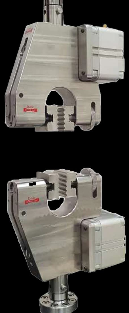
The fixture this method needs
Standard 25 mm
Pneumatic Vice Action Grip
Flat vice-action faces hold a die-cut rubber piece squarely at low force without pre-stressing it — the requirement here is a square, slip-free hold rather than the self-tightening action a tensile dumb-bell needs.
Reference to ASTM D624 and THE DIE USED — the result is meaningless without it
Compound identification and cure conditions
Cutting direction relative to the grain
Thickness at the tear path for each piece
Nick depth where the die is a nicked type
Test temperature
Crosshead rate
Whether peak or propagation force was taken
Tear strength in kN/m or N/mm
Number of pieces and the statistic reported
Any piece discarded because the tear left the intended path
What the machine must be capable of
Tear forces are small. A nominally 2.3 mm Die C specimen of ordinary rubber tears at roughly 20 N to 300 N, and only the toughest compounds approach 500 N, so clean resolution at the bottom of the scale matters far more than frame capacity; load cells from 100 N to 2 kN cover this work, and a 50 kN cell reads the whole test as noise. The method itself fixes no accuracy class, so the frame's force verification and the cell's low-end linearity carry the burden.
Speed is set by geometry: 500 ± 50 mm/min for Types A, B and C, 50 ± 5 mm/min for Types T and CP. Rubber is rate-sensitive, so running the wrong one of those two speeds gives a different number rather than a noisier one.
No extensometer and no strain measurement are required — only force and thickness. The demand falls on travel instead: trouser and constrained-path tears must be followed through the full propagation length, and soft compounds add large leg extension on top, so the frame needs long crosshead travel.
Grips must tighten as tension rises and press evenly across the gripping area. Pneumatic side-action grips are the usual answer, with self-tightening wedge and roller grips accepted alternatives. Faces must be wider than the specimen — 25 mm for Types A, B, C and CP, 30 mm for Type T — flat rubber faces for soft or easily damaged compounds, serrated or diamond faces for thick tough ones. For Types T and CP the two legs are clamped one per grip, symmetric about the machine axis. No dedicated tear fixture is needed beyond the grips; the geometry lives in the cutting die. Ambient testing needs no chamber; only non-ambient temperatures do.

What goes wrong in practice
Knotty tearing is the common one: the tear advances in stick-slip jerks and the trace returns saw-toothed, so which peak the operator reads changes the answer. Nick depth is next — a blunt blade or a nick cut too deep moves where the tear starts, and the scatter follows it. Soft compounds creep out of under-clamped grips, adding travel and losing force. Grain is the invisible one: cut every specimen the same way from a milled sheet and a direction-dependent compound reads as an isotropic one.
How it differs from the standards nearest to it
ASTM D624
ISO 34-1
ASTM D412
Measures
Tear strength
Tear strength
Tensile strength and elongation
Failure mode
A tear along a path
A tear along a path
Rupture across a section
Result units
Force per thickness, kN/m
Force per area, MPa
Geometry dependence
Total — five dies, five answers
Total — trouser, angle, crescent
Low, within a die
Comparable across geometries
No
No
Broadly, within a die
ISO 34-1 is the nearest counterpart and shares the principle, but the pieces and rates differ so the figures are not interchangeable. The deeper point applies to both: tear strength is a property of the compound AND the geometry together, which tensile strength very nearly is not.
Questions we are asked about this test
What is ASTM D624?+
It is the ASTM method for tear strength of vulcanised rubber and thermoplastic elastomers. A die-cut piece is pulled until a tear runs through it, and the force divided by the thickness at the tear path is the tear strength. Five die geometries are defined and each gives its own number.
Which die should I use for ASTM D624?+
Whichever the material specification names — this is not an operator's choice. Die C, the unnicked 90° angle, is the most commonly specified. Die T, the trouser, reports a propagation force rather than a peak and answers a different question about how an existing tear grows. The die must appear on the report, because the numbers do not convert between geometries.
Why is tear strength reported per thickness rather than per area?+
Because the specimen does not fail across a cross-section. A tear runs along a path, and the only meaningful dimension resisting it is the thickness through which it has to travel. That is why the units are kN/m or N/mm rather than MPa, and why the thickness is measured at the tear path specifically.
What is the difference between ASTM D624 and ASTM D412?+
They measure different failure modes. D412 pulls a dumb-bell until it ruptures across its section and reports a stress in MPa; D624 propagates a tear along a path and reports a force per thickness. A compound can be strong in tension and tear easily, which is exactly why both tests exist and why neither substitutes for the other.
What load cell does ASTM D624 need?+
A small one. A nominally 2.3 mm Die C specimen of ordinary rubber tears at roughly 20 N to 300 N, and only the toughest compounds approach 500 N. Cells from 100 N to 2 kN cover this work, and clean resolution at the bottom of the scale matters far more than capacity — a 50 kN cell reads the whole test as noise.
Why did my tear strength come out low?+
Two common causes. A burred cutting die leaves an edge that seeds a competing tear, so the piece fails early along a path the method did not intend. And slow data capture rounds off the brief peak that a crescent or angle die produces, which under-reports the maximum. Both errors are systematic and both push the result in the same direction.
What happens if the tear leaves the intended path?+
The result is unusable and the piece is discarded rather than recorded. A tear that wanders has measured the geometry of its own path rather than the compound's resistance, and averaging it in with valid results simply drags the mean toward a number that describes nothing.
Dak verifies against whichever standard the method names, and where a class applies our frames sit a class tighter than it asks.
The method asks for
Dak supplies
Capacity
Tear forces are small. A nominally 2.3 mm thick Die C specimen of ordinary rubber tears at roughly 20–300 N, and only the toughest compounds approach 500 N, so clean resolution at the bottom of a 500 N or 1 kN load cell matters far more than frame capacity; equipment vendors commonly fit 100 N to 2 kN cells for this work.
Load cells from 1 kg to 60 ton on the Series 7200, and 0.5 to 100 kN on the Series 9000
Force accuracy
unknown
ISO 7500-1 Class 0.5 — the method sets no class of its own
Gripping
Self-tightening tensile grips (pneumatic side-action, wedge or roller) with faces wider than the specimen; geometry supplied by the Type A/B/C/T/CP cutting die, not by a fixture
Ambient — condition and test at the standard test temperature of 23 ± 2 °C (ASTM D1349); an environmental chamber only for non-ambient test temperatures
This page describes the method as practised. The governing text is the current edition from the issuing body. Tell us what you are testing and we will answer with the machine, the fixture and a quotation.