
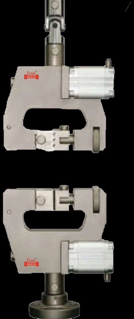
HJ-42
Light Duty Pneumatic Grip
25 mm square flat faces and air-driven closure. Every specimen sees the same clamping force, which matters here because grip separation is also the extension measurement.
Specifications
Testing standard
Standard Test Method for Tear Resistance (Graves Tear) of Plastic Film and Sheeting
Written and technically reviewed by Dak System Inc. engineeringLast reviewed
ASTM D1004 measures the force needed to start a tear in flexible plastic film and sheeting. A die-cut specimen carrying a sharp 90° angle is pulled apart at 51 mm/min, and the peak force — normally reached just as tearing begins — is reported as the tear resistance in newtons. It ranks materials of similar composition; it does not predict service tear performance.
From the test method to your testing system
Explore the DAK machines already listed for ASTM D1004, then review the grips, measurement and setup requirements below.
 Universal Testing MachineSeries 7200Explore the machine →
 Universal Testing MachineSeries 9000Explore the machine →
01Understand the method
A specimen is die cut to a shape carrying a 90° angle at one edge, honed sharp so the tearing force is concentrated into a very small region rather than spread along a cut. It is clamped at a short initial grip separation and pulled at a constant, deliberately slow rate until it fails. The peak force, normally reached close to the onset of tearing, is the tear resistance. Extension is taken from grip separation rather than from an extensometer, because this geometry has no gauge length worth instrumenting.
The force required to start a tear, as distinct from the force required to keep one running. That distinction is the reason two tear methods exist for film: a sealed pouch, a liner or a carrier bag most often fails because something initiates a tear at an edge or a fold, and initiation is what this geometry probes. The method's own scope is careful about what the number can be used for — it furnishes comparative information for ranking specimens of similar composition, and service performance need not follow it. It is reliable for materials that neither fail brittlely nor stretch enormously; the method excludes brittle failures and specimens whose maximum extension exceeds 101.6 mm.
Two limits govern how the number may be quoted. Tear resistance depends partly on thickness but has no simple relationship with it, so the result is reported as a force and never normalised per unit thickness unless a correlation has been established for that material. Results are therefore comparable only across specimens whose thickness stays within ±10 % of the average for the set.
02Prepare the specimen and test settings
The whole method rests on the die. The geometry exists to force the tear to start in one tiny region, and a die that has lost its edge changes the answer without changing anything you can see.
The exact die dimensions and tolerances are tabulated in the standard. A die that has been reground has not necessarily been returned to the drawing, and results before and after are not comparable until it has been checked.
Unlike most tensile methods, this one gives a single rate. It is deliberately slow, so the tear initiates under a controlled stress concentration rather than under an impact.
51 mm/min is far below any rate a film meets in service. That is the design of the method, and it is also why a D1004 figure is a ranking rather than a performance prediction.
03Build the test setup on a DAK machine
Very little force and a great deal of resolution. Tearing a thin film is a few newtons of work, so the load cell has to be chosen for the specimen rather than for the frame — a cell sized to the machine's headline capacity cannot resolve a peak of this size, and the peak is the entire result. A constant rate of grip separation of 51 mm/min is required, with an initial grip separation of 25.4 mm, so the machine needs stable low-speed control rather than range.
Grips must hold thin, slippery film without cutting it. Rubber-faced or flat-faced vice-action jaws closing on a light, repeatable clamping force are the usual answer; serrations that suit a rigid dumbbell will start a tear at the jaw on film. Because the whole extension is measured as grip separation, any slip is read as extension and quietly corrupts the record of where the peak fell.
25 mm square flat faces and air-driven closure. Every specimen sees the same clamping force, which matters here because grip separation is also the extension measurement.
Specifications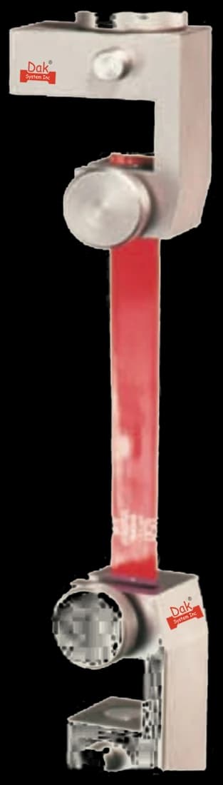
Rubber-coated faces hold thin film and slip-additive film without the serration marks that start a tear at the jaw rather than at the die angle.
SpecificationsA low-range cell. Tearing a thin film is a few newtons of work, and a cell sized for the frame throws away the resolution the peak is read from.
SpecificationsDak verifies against whichever standard the method names, and where a class applies our frames sit a class tighter than it asks.
| The method asks for | Dak supplies | |
|---|---|---|
| Capacity | A few newtons on thin film, rising into the tens of newtons on the thickest sheeting in scope, so the load cell is chosen for the specimen rather than for the frame; resolution at the bottom of the range decides whether the peak is usable. | Load cells from 1 kg to 60 ton on the Series 7200, and 0.5 to 100 kN on the Series 9000 |
| Force accuracy | ASTM E4 | Verified to ASTM E4, and to ISO 7500-1 Class 0.5 |
| Gripping | Flat or rubber-faced film grips closing on a light, repeatable clamping force, plus a die cutting the angled specimen with its 90° corner honed sharp | Our vice-action grips, built to the specimen |
| Environment | Conditioning to Practice D618, with the test run in the same atmosphere | 3009 series chambers, −150 °C to +400 °C — temperature only |
04Run the test
A specimen that slips at the jaw produces a curve that looks entirely normal and a peak that arrives late. If maximum extension scatters far more than the force does, suspect the grips before the material.
05Calculate, report and interpret
There is almost nothing to calculate, and the one temptation — dividing by thickness — is the thing the method warns against.
The maximum force recorded, in newtons
Reported as a force. There is no area term and no gauge length.
The maximum extension recorded, in millimetres
Read after complete rupture and reported alongside the force. Because it is grip travel, any slippage is counted as extension.
Only where a correlation has been established for that material
Tear resistance depends partly on thickness but has no simple relationship with it, so normalising across a wide thickness range produces misleading numbers.
A worn die, which is invisible and systematic. Clamping pressure set by feel, so the film creeps at the jaw and the trace acquires a shoulder that is not the specimen. Averaging machine-direction and transverse specimens into a single figure, which describes no direction the film actually has. Dividing the force by the thickness to make two materials comparable, which the method specifically warns against. And running a set whose thicknesses straddle more than ±10 % of their own average, which makes the specimens incomparable with each other.
06Compare methods and find answers
Two questions are asked about a tear, and they need different specimens. Buying one number when the specification wanted the other is a common and expensive mistake.
| ASTM D1004 | ASTM D1938 | ISO 6383-1 | ASTM D624 | |
|---|---|---|---|---|
| Question answered | Force to start a tear | Force to keep a tear running | Force to keep a tear running | Tear strength of rubber |
| Specimen | Angled die-cut piece with a 90° corner | Trouser specimen with a slit | Trouser specimen with a slit | Die-cut, several types |
| Loading | Constant rate of grip separation | Legs pulled apart | Legs pulled apart | Tension to failure |
| Result | Peak force, in N | Propagation force, in N | Propagation force, in N | Force per unit thickness |
| Normalised by thickness | No | No | No | Yes |
An easy-open pack that tears too readily and one that will not start tearing at all are opposite defects. D1004 speaks to the second, D1938 and ISO 6383-1 to the first.
It is the ASTM method for the tear resistance of flexible plastic film and sheeting, commonly called the Graves tear. A die-cut specimen with a sharp 90° angle is pulled at 51 mm/min and the peak force needed to start the tear is reported in newtons. The current edition is D1004-21.
They measure opposite halves of the same behaviour. D1004 uses an angled specimen to find the force required to initiate a tear; D1938 uses a trouser specimen with a slit already cut, so what it measures is the force required to keep an existing tear propagating. A film can be good at one and poor at the other, which is exactly why both methods exist.
51 mm/min, or 2 in./min, with an initial grip separation of 25.4 mm. It is a single fixed rate rather than a table of options, and it is deliberately far slower than any tearing a film meets in service — the point is to initiate the tear under a controlled stress concentration, not to reproduce a real event.
Only if a correlation has been established for that particular material. Tear resistance depends partly on thickness but not in any simple proportion, so normalising into a force per unit thickness across a range of gauges produces misleading figures. The method also restricts comparisons to specimens whose thickness stays within ±10 % of the set average.
Because the result is set by the stress concentration at the 90° corner, and the corner must be sharp with no more radius than the cutting process forces. A die that has blunted spreads the load over a slightly larger region, raises the measured force, and gives no sign of doing so. Dies are checked and re-measured rather than trusted.
At least ten for an isotropic material, and a minimum of ten in each of the machine and transverse directions for an anisotropic one — which extruded film is, so twenty is the working minimum. Materials whose properties vary considerably across the web need many more than that before a mean is worth quoting. Specimens that break at an obvious flaw, or in or at the edges of the grips, are discarded and replaced.
ASTM records that there is no known ISO equivalent to this test method. The nearest international documents are the trouser-tear methods such as ISO 6383-1, which answer the propagation question rather than the initiation question, so they are alternatives on a specification only if the specification actually wanted propagation.
A small universal testing machine with stable low-speed control at 51 mm/min, light film grips, and a load cell chosen for the specimen rather than the frame. Peak forces are typically a few newtons, so resolution at the bottom of the range decides whether the result is usable — capacity is irrelevant here.
Yes. Up to and including the D1004-03 edition the method was published as Standard Test Method for Initial Tear Resistance of Plastic Film and Sheeting; the Graves Tear title arrives with D1004-07. The current title is Tear Resistance (Graves Tear) of Plastic Film and Sheeting. A specification citing the old wording is asking for the same method under a name ASTM has retired.
Discuss your specimen, test requirements and reporting needs with DAK engineering.
This page describes the method as practised. The governing text is the current edition from the issuing body. Tell us what you are testing and we will answer with the machine, the fixture and a quotation.