
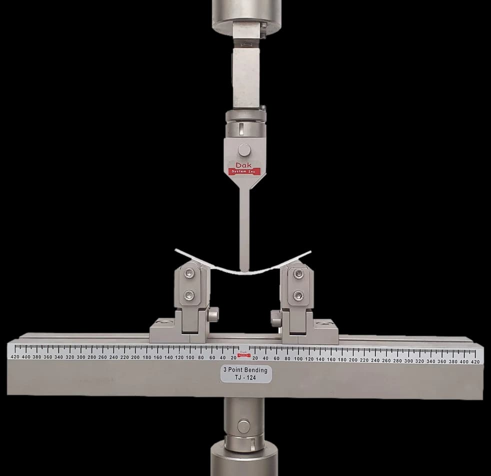
Adjustable spanTJ-124
Three Point Bend Fixture
A three-point bend fixture with adjustable span and the roller diameters the method specifies — span-to-depth ratio is set on the fixture, not assumed.
Specifications
Testing standard
Metallic Materials — Bend Test
Written and technically reviewed by Dak System Inc. engineeringLast reviewed
IS 1599 specifies the bend test for assessing a metallic material's ability to undergo plastic deformation in bending. It covers flat products, bars, rods and wire, and the current edition is dual-numbered with ISO 7438:2020.
From the test method to your testing system
Explore the DAK machines already listed for IS 1599, then review the grips, measurement and setup requirements below.
 Universal Testing MachineSeries 7200Explore the machine →
 Universal Testing MachineSeries 9000Explore the machine →
01Understand the method
A test piece — flat product, bar, rod or wire — has its edges rounded and is laid across two supports set at a clear distance of the former diameter plus three times the thickness. A former of the diameter fixed by the material's product standard is driven into it in one continuous movement to a specified angle, commonly 90° or 180°. The piece is then removed and its outer, stretched surface examined under magnification for cracks, which are judged against the acceptance criterion in the product standard rather than in this one.
Whether the material will take a bend without cracking — the question behind every folded bracket, formed section and bent reinforcement bar. What makes this page worth reading alongside the others is the dual numbering. An adopted standard normally drifts from its parent: IS 1969 (Part 1) is identical with ISO 13934-1 as it stood in 1999 while ISO has since issued a 2013 edition, and IS 3400 (Part 1) tracks an ISO 37 edition superseded twice over. Publishing one text under two designations removes that gap entirely, and a result is simultaneously an IS and an ISO result.
02Prepare the specimen and test settings
An adopted standard usually lags its parent. This one is published as the same document under two numbers.
The result is a pass or a fail on the condition of the outer surface, judged against the acceptance criterion in the product standard. This method supplies no criterion of its own.
The method sets no rate of traverse at all. It controls the geometry of the bend instead, and those are the figures a set-up sheet has to carry.
03Build the test setup on a DAK machine
Enough force to complete the bend — a thick plate or a large bar can need hundreds of kilonewtons — and the stroke to reach the specified angle in one continuous movement. Force accuracy matters less here than in most methods, since nothing is calculated from the load; what the frame needs is stability and travel. The formers themselves are the consequential hardware, because the diameter is the entire severity of the test and it comes from the product standard.
There is no rate of traverse to set, and that is the method rather than a gap here. The procedure requires only that the force increase continuously and be applied slowly enough to permit free plastic flow of the material; no speed, force rate or time appears anywhere in the text. What it does fix, and what a set-up sheet should carry, is geometry: the former diameter D, from the product standard and never from this one; the clear support distance l = D + 3a, where a is the thickness or diameter of the piece; the bend angle; one uninterrupted movement to it; and a temperature of 10 °C to 35 °C, or 23 ± 5 °C controlled. A slow crosshead of a few millimetres per minute satisfies free plastic flow on ordinary structural material, but that is a laboratory choice: record it as the speed used, never as a specified one.
A three-point bend fixture with adjustable span and the roller diameters the method specifies — span-to-depth ratio is set on the fixture, not assumed.
Specifications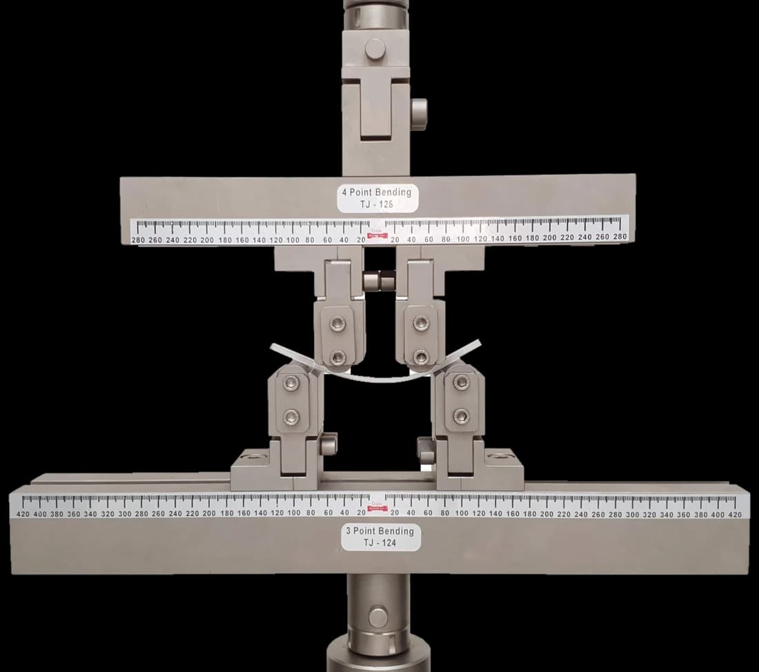
Four-point loading where the specification calls for it, putting a length of the specimen under constant moment rather than concentrating it under one nose.
SpecificationsDak verifies against whichever standard the method names, and where a class applies our frames sit a class tighter than it asks.
| The method asks for | Dak supplies | |
|---|---|---|
| Capacity | Moderate to high — a thick plate or a large bar can need hundreds of kilonewtons to bend | Load cells from 1 kg to 60 ton on the Series 7200, and 0.5 to 100 kN on the Series 9000 |
| Force accuracy | unknown — clause 4.1 specifies bending devices only and states no force-accuracy class; the test is controlled by geometry rather than by force | ISO 7500-1 Class 0.5 — the method sets no class of its own |
| Gripping | A bend former of the diameter the product standard fixes, with supports set to a clear distance | Our bend fixtures, built to the specimen |
| Environment | ambient temperature between 10 °C and 35 °C; tests under controlled conditions at 23 ± 5 °C (clause 6.1). No humidity is specified. Read from IS 1599-1985; the 2023 text is not publicly retrievable | 3009 series chambers, −150 °C to +400 °C — temperature only |
04Run the test
05Calculate, report and interpret
l = D + 3a
Sets the clearance between supports. Too close and the piece is sheared rather than bent.
Approximately a / (D + a)
Not reported by the method, but it is why a tighter former on a thicker piece is a far more severe test than the diameter alone suggests.
From the product standard, not from IS 1599
Using a former larger than the product standard specifies, which makes the test easier while leaving no trace in the report unless the diameter is recorded — which is why it is recorded. Sharp edges producing preparation cracks. Stopping mid-bend, which leaves a witness mark on the very surface being examined. Examining by eye rather than under magnification, when the defect sought is a fine crack on a work-hardened surface. And stating a pass without naming the document the acceptance criterion came from, since IS 1599 supplies none of its own. A quieter failure is recording the bend angle but not the former, when the former is the parameter that decided whether the piece could pass at all.
06Compare methods and find answers
| IS 1599 : 2023 | ISO 7438:2020 | |
|---|---|---|
| Relationship | Dual-numbered — the same text | Dual-numbered — the same text |
| Former diameter | From the product standard | From the product standard |
| Acceptance criteria | Not given | Not given |
| Drift risk | None while dual numbering holds | None while dual numbering holds |
This is the counter-example to the adopted-standard drift that IS 1969 and IS 3400 illustrate. Dual numbering publishes one text under two designations, so the Indian and ISO versions cannot diverge.
It is the Indian Standard bend test for metallic materials, assessing a material's ability to undergo plastic deformation in bending. It covers flat products, bars, rods and wire. The current edition, IS 1599 : 2023, is the fifth revision and is dual-numbered with ISO 7438:2020.
That the Indian and ISO documents are the same text published under two designations, rather than the Indian one being an adoption of a particular ISO edition. It matters because adopted standards normally drift: IS 1969 (Part 1) is identical with ISO 13934-1:**1999** while ISO has moved to 2013, and IS 3400 (Part 1) is aligned with an ISO 37 edition that has since been superseded twice. Dual numbering closes that gap.
From the product standard for the material, not from this one. IS 1599 supplies the method — how to set the supports, how to bend, what to examine — while the severity is set by whatever specification the material is supplied to. That is why a bend test report is incomplete without both the former diameter and the document it was taken from.
To give the piece room to bend rather than shear. If the supports sit too close to the former, the material is forced over a short span and fails by shearing across the supports instead of by stretching its outer surface, which is a different failure and not what the test is looking for. The formula scales the clearance with both the former size and the material thickness.
No. It gives no acceptance criterion. What counts as an acceptable outer surface after bending comes from the product standard or the contract, and a report that states a pass without naming where that criterion came from is claiming an authority the method does not have.
Because a sharp machined corner is a stress raiser at the very edge of the surface being stretched, and a crack that starts there is a preparation defect rather than a material one. Once it has run, the two are indistinguishable, and the test piece is lost. Rounding the edges beforehand removes a whole class of false failures.
Because a fine crack a few millimetres long on a deformed, work-hardened surface is genuinely easy to overlook, and it is exactly the defect the test exists to reveal. Examining by eye at arm's length passes material that should have failed, and nothing downstream will catch it.
Discuss your specimen, test requirements and reporting needs with DAK engineering.
This page describes the method as practised. The governing text is the current edition from the issuing body. Tell us what you are testing and we will answer with the machine, the fixture and a quotation.