
Rigidly fixedTJ-146
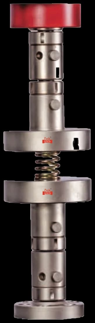
Compression Anvils
Flat, parallel, hardened anvils. Their parallelism is part of the method — an anvil out of true compresses one side of the specimen first and both percentages carry the error.
Specifications
Testing standard
Standard Test Method for Compressibility and Recovery of Gasket Materials
Written and technically reviewed by Dak System Inc. engineeringLast reviewed
ASTM F36 measures how much a gasket material compresses under load and how much of that compression it gets back. A specimen is loaded to a preload, then to a major load, then back to the preload, with thickness recorded at each step. Compressibility and recovery come out as percentages, and a gasket needs both — one to conform to the flange, the other to follow it.
From the test method to your testing system
Explore the DAK machines already listed for ASTM F36, then review the grips, measurement and setup requirements below.
 Universal Testing MachineSeries 7200Explore the machine →
 Universal Testing MachineSeries 9000Explore the machine →
01Understand the method
A gasket specimen is placed between two hardened anvils and a small preload is applied to establish a datum thickness. The load is then raised to a specified major load, held, and the thickness recorded again. The load is returned to the preload and, after a short recovery period, thickness is measured once more. Nothing is pulled and nothing fails — the whole test happens within the elastic and plastic response of the material.
Two figures come out: compressibility, the proportion of the original thickness lost under the major load, and recovery, the proportion of that loss regained when the load is removed. A gasket must compress enough to conform to flange irregularities and recover enough to follow the joint as bolts relax and the flange breathes with temperature. A material that compresses well and recovers poorly seals on assembly and leaks later, which is the failure this test exists to predict.
The two figures pull against each other, and that tension is the whole reason both are reported. A soft, highly compressible sheet conforms to a warped flange easily but has little left to give back; a dense, low-compressibility sheet recovers well but may never seat against the irregularity in the first place. A gasket specification therefore sets a window on each rather than a minimum on either, and a material can fail by being too compressible as readily as by being too little.
02Prepare the specimen and test settings
03Build the test setup on a DAK machine
Force demand is modest and the resolution requirement is severe: the preload must be applied repeatably and the thickness measured to a few micrometres, because both results are ratios of small differences. Anvils must be flat, parallel and hardened, and the deflection measurement must exclude the frame's own compliance — on a thin gasket the machine's flex can exceed the specimen's compression. A load cell of a few kilonewtons with clean low-end resolution is more useful here than a large one.
F36 fixes no crosshead speed. Its loading device has only to apply the major load at a slow uniform rate and to an accuracy of ±1 %. What is prescribed instead is the load schedule, and it varies by material class: compressed sheet, flexible graphite and compressed non-asbestos sheet are taken to 34,5 MPa (5 000 psi) total on a 6,4 mm penetrator, papers and millboard to 6,89 MPa, fluorocarbon sheet to 17,25 or 34,5 MPa, and cork composition to 0,69 MPa on a 28,7 mm penetrator. The major load is held for 60 s before the compressed thickness is read, and the recovered thickness is read 60 s after it is released.
Because both results are ratios of small differences, the measurement chain matters more than the frame. A thickness resolution of a few micrometres is needed on a specimen that may only be a millimetre or two thick, and the deflection has to be read across the anvils rather than inferred from crosshead position — the frame's own flex under the major load is comparable with the compression being measured. The preload has to be repeatable to the same precision, since it sets the datum every later figure is referred to.
Flat, parallel, hardened anvils. Their parallelism is part of the method — an anvil out of true compresses one side of the specimen first and both percentages carry the error.
Specifications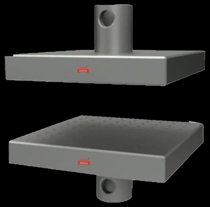
Direct compression platens where the specimen is larger than the standard anvils cover.
SpecificationsDak verifies against whichever standard the method names, and where a class applies our frames sit a class tighter than it asks.
| The method asks for | Dak supplies | |
|---|---|---|
| Capacity | Modest — the specified major load on a small disc, commonly well under 10 kN. Resolution on thickness matters far more than capacity. | Load cells from 1 kg to 60 ton on the Series 7200, and 0.5 to 100 kN on the Series 9000 |
| Force accuracy | unknown — ASTM E4 is not among this method's referenced documents, which name no force-verification standard and no accuracy class | ISO 7500-1 Class 0.5 — the method sets no class of its own |
| Gripping | Flat, parallel, hardened compression anvils covering the specimen fully. | Our compression anvils, built to the specimen |
| Environment | Ambient: standard laboratory atmosphere. Many gasket materials are hygroscopic. | 3009 series chambers, −150 °C to +400 °C — temperature only |
04Run the test
05Calculate, report and interpret
C = ((t₁ − t₂) / t₁) × 100
R = ((t₃ − t₂) / (t₁ − t₂)) × 100
A percentage of what was LOST, not of the original thickness. A material that compresses 40 % and recovers 50 % has come back 20 % of its original thickness — the two figures have to be read together.
Machine compliance is the classic error: crosshead travel includes the frame's stretch, so compressibility reads high and recovery low unless the deflection is measured across the anvils themselves or the compliance is subtracted. Uneven anvils compress one side first. Rushing the recovery period reports less recovery than the material has. And using a micrometer thickness instead of the preload thickness makes the datum incomparable with anybody else's.
Two further faults recur beyond the obvious ones. Anvils that no longer sit parallel compress one edge of the disc first, so the recorded thickness change is an average across a wedge rather than a uniform compression, and the effect is invisible in the numbers. And specimens punched with a blunt die carry a compressed rim that behaves quite differently from the body of the material, which shows up as scatter between nominally identical discs rather than as an obviously wrong result.
06Compare methods and find answers
Two gasket properties that only mean something as a pair.
| ASTM F36 | ASTM F38 | |
|---|---|---|
| Measures | Compressibility and recovery | Creep relaxation |
| Timescale | Minutes | Hours, often at temperature |
| Answers | Will it conform, and spring back? | Will it stay loaded? |
| Failure it predicts | Poor initial seal | A leak after a thermal cycle |
A material with excellent compressibility and poor relaxation resistance seals beautifully on assembly and leaks a month later. Qualifying a gasket on F36 alone is how that gets missed.
It is the ASTM test method for compressibility and recovery of gasket materials. A specimen is loaded to a preload to establish a datum thickness, then to a specified major load, then back to the preload, with thickness recorded at each stage. The results are compressibility and recovery, both as percentages.
Because a compressible material reads differently under any two gauges — a micrometer at whatever pressure the operator applies gives a thickness nobody else can reproduce. Taking the datum under a defined preload makes it a repeatable measurement, and it is why the preload is specified rather than nominal.
Whether the gasket will seal and stay sealed. Compressibility says whether it will conform to flange irregularities; recovery says whether it will follow the joint as bolts relax and the flange moves with temperature. A material that compresses well and recovers poorly seals on assembly and leaks later.
Of the thickness LOST under the major load, not of the original thickness. A gasket that compresses 40 % and recovers 50 % has regained 20 % of its original thickness. Reading recovery as a fraction of the original overstates it substantially, and it is a common misreading.
Because on a thin gasket the frame's own stretch can exceed the specimen's compression. If deflection is taken from crosshead travel, the machine's flex is counted as gasket compression — so compressibility reads high and recovery reads low, and both errors point the same way. Measuring across the anvils removes it.
There is no thickness limit in principle, but thin sheet is where the method gets difficult. Both results are ratios of small differences, so on a one-millimetre gasket the compression may be tens of micrometres — comparable with the frame's own flex under load. That is why the deflection is read across the anvils and why the preload must be repeatable to the same precision as the measurement.
Only partly, and that is the point of reading it with ASTM F38. Compressibility says the gasket will conform to the flange and recovery says it will follow the joint as it moves, but neither says how much load it will still be carrying next month. A material can pass both handsomely and relax badly, which is the field failure the pair together is meant to catch.
Discuss your specimen, test requirements and reporting needs with DAK engineering.
This page describes the method as practised. The governing text is the current edition from the issuing body. Tell us what you are testing and we will answer with the machine, the fixture and a quotation.