
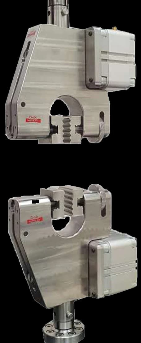
Standard 25 mm
Pneumatic Vice Action Grip
Constant air pressure across the full jaw face holds a thin film tail without cutting it — a seal test that fails at the grip has measured the grip.
Specifications
Testing standard
Standard Test Method for Seal Strength of Flexible Barrier Materials
Written and technically reviewed by Dak System Inc. engineeringLast reviewed
ASTM F88 measures the seal strength of a flexible barrier material — the force needed to pull a defined width of seal apart. A strip cut through the seal is clamped by its two tails and separated at a constant rate. It reports maximum force, average force, or the whole curve, together with the failure mode, which is the diagnostic half of the result.
From the test method to your testing system
Explore the DAK machines already listed for ASTM F88, then review the grips, measurement and setup requirements below.
 Universal Testing MachineSeries 7200Explore the machine →
 Universal Testing MachineSeries 9000Explore the machine →
01Understand the method
A strip is cut across a sealed area of a package so the seal runs through its middle. The two unsealed tails are clamped in opposing grips with the seal roughly midway between them, and the crosshead separates the grips at a constant rate until the seal pulls fully apart. Force against grip separation is recorded throughout, so the whole peel trace is captured, not just the peak.
The method reports seal strength — the force needed to pull a defined width of seal apart — as maximum, average or the whole force curve, together with the failure mode observed. Maximum force is what medical device and pharmaceutical manufacturers use for lot release and for validating a sealing process window against a specification. Average force describes how a peelable seal opens in a clinician's hands, which is a usability question rather than a strength one. Failure mode is the diagnostic half of the result: the same peak force means something different if the film tore instead of the seal peeling.
02Prepare the specimen and test settings
03Build the test setup on a DAK machine
Seal forces are light. Medical device seals commonly peak between about 4 and 9 N per 15 mm strip, pharmaceutical seals a little higher, and tough laminates or tray lidding run to a few tens of newtons, so a 50 N to 500 N load cell on a single-column frame is the normal fit rather than a general-purpose high-capacity frame. Force resolution at the bottom of the range matters more than headroom: a peel trace read on a 5 kN cell resolves nothing useful. The method does not itself set an accuracy class, so the applicable force-verification requirement comes from the laboratory's quality system.
Grip separation runs at 200 to 300 mm/min (8 to 12 in./min). Travel demand is short — full separation normally occurs within 50 mm of crosshead movement — but the initial grip separation is a required reporting item, so it has to be set and logged rather than assumed. No extensometer is involved; peel is a force-against-displacement measurement, not a strain one.
Fixturing is what the three techniques differ on. Technique A leaves the seal unsupported between the grips; Technique B supports it perpendicular to the tails at 90°; Technique C folds the more flexible tail 180° back over the seal with the stiffer member held flat, and the 2023 edition adds two Technique C approaches for flexible-to-rigid and semi-rigid trays using alignment plates. Opposing side-action grips, commonly pneumatic, hold the tails at constant clamping force. Mixing techniques within a series destroys comparability.
Constant air pressure across the full jaw face holds a thin film tail without cutting it — a seal test that fails at the grip has measured the grip.
Specifications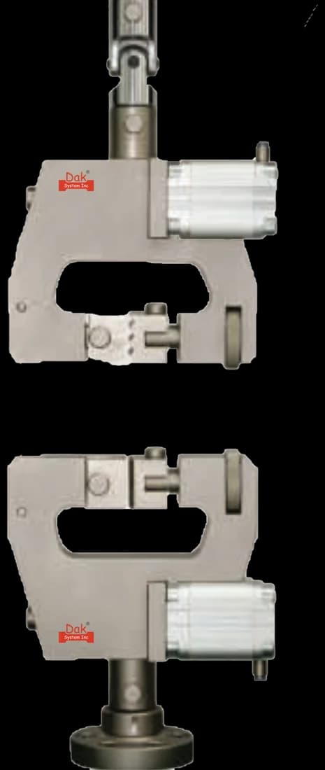
Light duty closure for the lowest seal strengths, where a heavier grip would damage the web before the seal is loaded.
SpecificationsDak verifies against whichever standard the method names, and where a class applies our frames sit a class tighter than it asks.
| The method asks for | Dak supplies | |
|---|---|---|
| Capacity | Very light forces — medical device seals commonly peak around 4 to 9 N per 15 mm strip and pharmaceutical seals a little higher, with tough laminates and tray lidding running to a few tens of newtons, so a 50 N to 500 N load cell on a single-column frame is the normal fit. | Load cells from 1 kg to 60 ton on the Series 7200, and 0.5 to 100 kN on the Series 9000 |
| Force accuracy | unknown | ISO 7500-1 Class 0.5 — the method sets no class of its own |
| Gripping | Opposing side-action grips with the seal centred, plus a 90° or 180° seal support (alignment plates) for Techniques B and C | Our vice-action grips, built to the specimen |
| Environment | Condition per ASTM E171 and test at ambient — seal strength is defined as the tensile strength of the seal at ambient temperature | 3009 series chambers, −150 °C to +400 °C — temperature only |
04Run the test
The same peak force means something quite different if the film tore instead of the seal peeling. A tear can read higher than a clean peel while representing a package that will fail unpredictably, which is why the failure mode is not optional.
05Calculate, report and interpret
S = F / w
Maximum force is the lot-release figure. Average force describes how a peelable seal opens in a clinician's hands, which is a usability question rather than a strength one — the two answer different questions and both may be required.
Bending force is the standard bias: in Technique A the tails flex as they load, and that parasitic bending adds to the reading, so unsupported results sit above supported ones on the same seal. Film tear instead of seal peel gives a high number that describes the substrate, not the seal. Delamination — laminate layers separating internally — reads as a low, ragged trace and is often logged as a weak seal when the seal never failed. Slipping tails give a false early peak.
06Compare methods and find answers
| ASTM F88 seal strength | Seal integrity tests | |
|---|---|---|
| Question answered | How strong is the seal? | Is there a leak path? |
| Destructive | Yes | Some are, some are not |
| Detects a channel leak | Not reliably | Yes — that is the point |
| Used for | Process validation and lot release | Package integrity assurance |
A strong seal and an intact seal are different claims. F88 can pass a package that carries a narrow channel leak, because the surrounding seal still carries the load — which is why sterile barrier programmes run integrity testing alongside it rather than instead of it.
It is the ASTM test for seal strength of flexible barrier materials. A strip cut across a seal is clamped by its two tails and pulled apart at a constant rate, and the method reports the force needed to separate a defined width of seal, together with the failure mode.
How the tails are supported. Technique A leaves them unsupported, B supports them at 90° and C at 180°. Support changes the peel angle at the seal and therefore the force, so the three are not interchangeable — a specification quoting a seal strength has to name the technique it was measured under.
It depends on the question. Maximum force is what medical device and pharmaceutical manufacturers use for lot release and for validating a sealing process window. Average force describes how a peelable seal opens in a clinician's hands, which is usability rather than strength. Many specifications call for both.
Because the same peak force can mean opposite things. A seal that peels cleanly and a film that tears can record similar numbers, but a tearing web indicates a package that will fail unpredictably in handling. Recording only the force throws away the part of the result that tells you whether the package is sound.
No, and this is the most consequential misunderstanding about the test. F88 can pass a package carrying a narrow channel leak, because the surrounding seal still takes the load. Seal strength and seal integrity are different claims, which is why sterile barrier programmes run integrity testing alongside F88 rather than treating one as evidence of the other.
Because seal strength varies with position under the sealing jaws — temperature, pressure and dwell are never perfectly uniform across a long seal or around a pouch. A single specimen from a convenient spot characterises that spot. Sampling from each seal and along its length is what turns the test into process validation.
Discuss your specimen, test requirements and reporting needs with DAK engineering.
This page describes the method as practised. The governing text is the current edition from the issuing body. Tell us what you are testing and we will answer with the machine, the fixture and a quotation.