Testing standard

ISO 2307

Fibre ropes — Determination of certain physical and mechanical properties

Written and technically reviewed by Dak System Inc. engineeringLast reviewed

ISO 2307 determines six properties of a fibre rope in one procedure: linear density, diameter, lay length, braid pitch, elongation and breaking force. Every dimensional measurement is taken at a calculated reference tension, and the breaking force is reported for each test piece as spliced or unspliced, never averaged. The current edition is ISO 2307:2019.

At a glance

Test type
Tensilethe specimen is pulled apart
Published by
ISO
Edition
ISO 2307:2019

What the test does

A length of rope is taken at random from a manufacturing batch, laid out straight, marked and mounted at a defined effective length between its terminations. A reference tension is applied, and the diameter, the lay length or braid pitch and the gauge length between the marks are all measured while the rope is held under it. The rope is then bedded in by cycling ten times — or three times, as the alternative the method allows — between the reference tension and half the minimum specified breaking force. The gauge length is measured again at that half-load point to give elongation, then the tension is raised at the same speed until the rope breaks. Linear density is determined separately, on a fresh two-metre length weighed after being held at the reference tension.

What it measures, and why it matters

Six properties in one document: linear density, diameter, lay length, braid pitch, elongation and breaking force, with methods for water repellency and for lubrication and finish content added for natural-fibre ropes when a customer asks for them. They travel together because none of them is defined without the others. An unloaded rope has no measurable diameter and no measurable length — it shortens and fattens the moment tension comes off — so every dimensional measurement is taken at a reference tension calculated from the rope reference number, never chosen by the operator. The breaking force is reported for each test piece and deliberately not averaged, and it has to be stated as spliced or unspliced, because the termination is part of the result rather than a detail of the rigging.

Test piece and terminations

The termination is part of the specimen. Most of the specimen rules exist to stop the rope breaking in the eye or at the grip instead of in the rope.

Effective length between terminations
At least 5 lays or braid pitches, or 400 mm, whichever is greater
Marked gauge length
Greater than 400 mm, symmetrical about the mid-pointTwo w marks. Where the effective length is under 400 mm, the gauge measurements are made on a separate piece.
Eye splices
Made to the rope manufacturer's instructions; internal eye length in principle at least 6 times the rope diameter when closedA splice designed to enhance performance during testing is specifically excluded — it must be a splice suitable for general rope service.
Break-zone marks
2 to 3 rope diameters from the end of the splice or the bollard tangent point
Number of test pieces
One from each sample; samples taken at random from a homogeneous batch
Conditioning
Ambient atmosphere; ISO 139 for at least 48 h in cases of dispute
Mark an alignment line along the rope before mounting
The line must be straight once the rope is on the bed. A twisted mounting puts torque into a structure that answers torque by unlaying.

Handle the test piece so it cannot unlay. A rope that has started to open at the cut end is no longer the rope that left the machine.

Reference tension, bedding-in and test speed

Reference tension
F_T = (n_ref² / 8) × 0,01 kN, tolerance ±5 %n_ref is the rope reference number. Annex A tabulates the nominal values. This is the tension at which linear density, diameter and lay length are measured.
Bedding-in
10 cycles between the reference tension and 50 % of the minimum breaking force; 3 cycles by agreementThe number of cycles used must be recorded in the test report.
Speed, wedge or bollard grips
250 mm/min ± 50 mm/min
Speed, spliced ropes on pins
2 % to 12 % of the pin-to-pin length per minute
Elongation measured at
50 % of the minimum specified breaking forceAdditional measurements may optionally be taken in increments, for example every 10 % from 10 % to 50 % of the minimum specified breaking force.
Measure elongation without approaching the loaded rope
The standard asks for an optical tracking system or a displacement transducer wherever possible, and says the practice of approaching a rope under load shall be avoided.

Calculations

Reference tensionF_T

F_T = (n_ref² / 8) × 0,01

F_T
reference tension, kN
n_ref
reference number of the rope

Applied when measuring linear density and lay length or braid pitch. Tabulated in Annex A with a ±5 % tolerance.

Linear densityρ₁

ρ₁ = m / l₁

m
mass of the test piece, g
l₁
measured length under the reference tension, m

Expressed in kilotex. Measured on a fresh length of 2 m or more, not on the piece that was broken.

ElongationE

E = ((l₃ − l₂) × 100) / l₂

l₂
gauge length at the reference tension, mm
l₃
gauge length at 50 % of the specified minimum breaking force, mm

Both lengths are measured between the same two w marks, so the elongation is referred to the rope under tension rather than to a slack length.

Lay lengthl_p

l_p = l_n / n

l_n
length of n complete turns of the same strand, or n successive plait points, mm
n
number of turns or plait points measured
Breaking force

The maximum force recorded, expressed in kilonewtons

Reported for each test piece individually. The mean is not calculated, and the report must say whether the value is spliced or unspliced.

How the test runs

  1. 01Take samples at random from a homogeneous manufacturing batch.
  2. 02Cut one test piece per sample, preventing the ends from unlaying.
  3. 03Mark an alignment line along the rope, and two w marks more than 400 mm apart.
  4. 04Make eye splices to the manufacturer's instructions if testing on pins.
  5. 05Mount the piece to give the required effective length, with the alignment line straight.
  6. 06Add the r marks 2 to 3 rope diameters from the splice or tangent point.
  7. 07Apply the reference tension and measure diameter, lay length or braid pitch, and the gauge length l₂.
  8. 08Bed the rope in by cycling between the reference tension and 50 % of the minimum breaking force.
  9. 09Raise the tension at the specified speed and measure l₃ at 50 % of the minimum breaking force.
  10. 10Continue at the same speed to rupture, recording the maximum force and where the break occurred.
  11. 11Determine linear density on a separate 2 m length held at the reference tension.
  12. 12Report each breaking force separately, stating spliced or unspliced and the number of bedding-in cycles.

A rope taken to rupture in more than one pull can give a different result. The stroke and bed length have to allow one continuous pull.

Grips and fixtures for this method

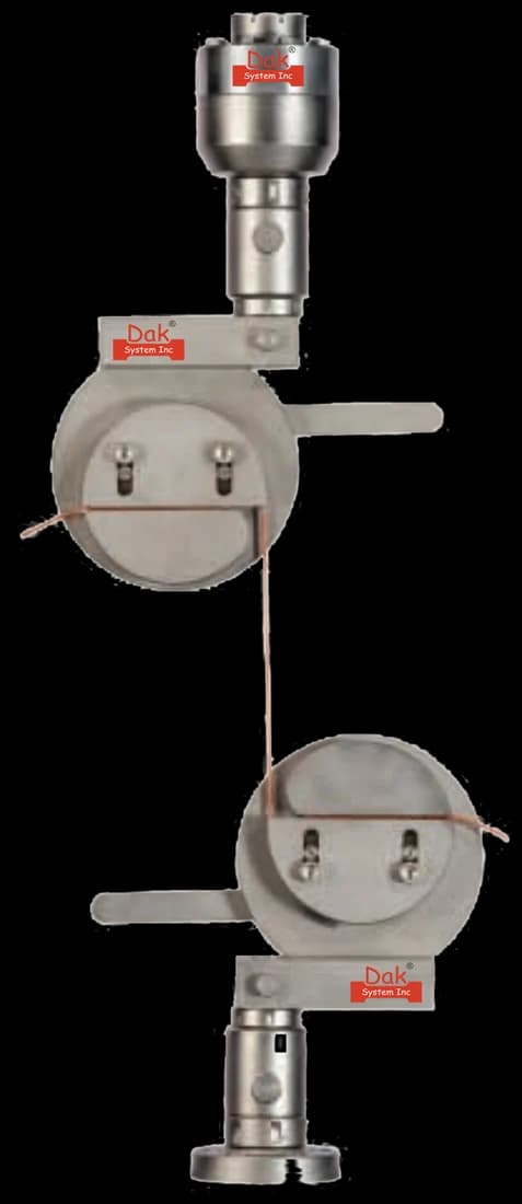
Split capstan grips for rope, cord and yarn
Constant pressureTJ-27

Split Capstan Grips

Rope, cord and twine are clamped against a curved capstan body, so the force enters the rope gradually along the wrap instead of at one short clamped section. That is what stops the break happening at the grip rather than in the rope.

Specifications
Self-identifying

Load Cells

ISO 2307 asks for the breaking force to be measured to ±1 %, so the cell has to be chosen for the rope rather than for the frame. Rope sizes across a range means more than one capacity.

Specifications

What the report has to contain

  • Reference to ISO 2307 and the edition
  • Rope identification, construction and reference number
  • Reference tension applied
  • Diameter, and lay length or braid pitch
  • Linear density in kilotex
  • Effective length and gauge length used
  • Number of bedding-in cycles
  • Test speed, the grip arrangement used, and the D/d ratio where bollards were used
  • Elongation at 50 % of the minimum breaking force
  • Breaking force for each test piece, in kilonewtons
  • Whether each breaking force is spliced or unspliced
  • Where the break occurred, relative to the r marks
  • The splice method, where it departs from the manufacturer's instructions
  • A statement if Annex B was used to derive strength from yarn results

What the machine must be capable of

Force, stroke, and a termination that does not become the specimen. The machine must measure the breaking force to ±1 %, and the stroke and bed length should be long enough to take the rope to rupture in one continuous pull; the standard notes that a specimen broken over more than one pull can give a different answer. Three arrangements are recognised — bollard-type grips, pins for eye splices, and wedge grips. A bollard or capstan must be at least ten times the rope diameter and a pin at least twice it. Speed goes with the arrangement: 250 mm/min ± 50 mm/min on wedge or bollard grips, and 2 % to 12 % of the pin-to-pin length per minute for spliced ropes.

What goes wrong in practice

Breaking in the eye or at the termination, which is what the splice rules exist to prevent — a break outside the marked zone is accepted only at 90 % or more of the specified value, and the standard warns against scaling such a result up by 10/9 to rescue it. Shortening the bedding-in, so the reported elongation still contains the constructional stretch the cycling was there to remove; the cycle count belongs in the report for that reason. Measuring diameter with no tension on the rope. Averaging the breaking forces, which the method does not ask for. And walking up to a loaded rope to read a gauge length by hand, which is the one item here that injures people rather than results.

Three ways of holding a rope

The standard recognises three machine types, and each brings its own rule about how big the termination has to be.

Bollard gripsPins for eye splicesWedge grips
TerminationRope wrapped on the bollardEye splice over a pinRope clamped in wedges
Size ruleBollard at least 10 × rope diameterPin at least 2 × rope diameterNo diameter rule stated
Test speed250 mm/min ± 50 mm/min2 % to 12 % of pin-to-pin length per minute250 mm/min ± 50 mm/min
Typical useRopes below reference number 20Ropes of reference number 20 and aboveRopes below reference number 20

The termination decides the number. A spliced breaking force and an unspliced breaking force are different quantities, and a report that does not say which was measured cannot be checked against a specification.

Questions we are asked about this test

What is ISO 2307?

ISO 2307 is the international method for determining certain physical and mechanical properties of fibre ropes: linear density, diameter, lay length, braid pitch, elongation and breaking force. The current edition is ISO 2307:2019, the fifth, which replaced ISO 2307:2010 and was confirmed on systematic review in 2025.

What is the reference tension, and why does everything depend on it?

It is a small tension, calculated from the rope's reference number as the reference number squared divided by eight, times 0,01, in kilonewtons. It exists because an unloaded rope has no defined size: it shortens and thickens as soon as tension comes off. Diameter, lay length, braid pitch, linear density and the gauge length for elongation are all measured with the rope held at that tension, so two laboratories measuring the same rope arrive at the same figures.

Why is the rope cycled before it is broken?

To take the constructional stretch out. A new rope contains slack that is bedded down the first few times it is loaded, and elongation measured without that step is mostly a measurement of the rope tightening rather than of the fibre stretching. The method calls for ten cycles between the reference tension and half the minimum breaking force, or three by agreement, and the number used has to be stated in the report because it changes the answer.

What is the difference between spliced and unspliced breaking force?

Whether the rope was terminated with an eye splice or held directly. A splice reduces the strength of a rope, so the two numbers are not the same and a specification names one of them. ISO 2307 requires the report to say which was measured. For an unspliced value the break must fall inside the marked zone, or outside it at 90 % or more of the specified value.

Can a break outside the marked zone be scaled up to a pass?

No. The standard allows a break outside the r marks to count if it reaches at least 90 % of the specified value, and then says explicitly that it should not be assumed the true breaking force would be found by multiplying the result by 10/9. The allowance exists to avoid discarding a valid test, not to convert a low result into a passing one.

What test speed does ISO 2307 use?

It depends on how the rope is held. On wedge grips or bollard grips the speed should be 250 mm/min ± 50 mm/min. On spliced ropes tested over pins it should be between 2 % and 12 % of the pin-to-pin length per minute. Either may be varied if it is specified and documented in the test report. The fifth edition changed the test speed, so a figure from the 2010 edition was not produced this way.

How long does the test piece have to be?

The effective length between terminations must be at least five lays or braid pitches, or 400 mm, whichever is greater, and the marked gauge length inside it must exceed 400 mm. In practice the machine has to be long enough that the rope reaches rupture in one continuous pull, because the standard notes that breaking a specimen over more than one pull can affect the result.

Are the breaking forces averaged?

No, and this catches people out. Linear density, lay length and elongation are reported as the arithmetic mean of the test pieces in the batch, but the breaking force is reported for each test piece individually with no mean calculated. If one test falls below the minimum breaking strength the manufacturer may run two further tests, and the rope passes only if both of those are above it.

What if the rope is too strong to break whole?

Annex B of ISO 2307 gives alternative procedures for ropes with high breaking forces, which derive the rope strength from yarn test results. Those procedures are available only by agreement between the parties, and where they are used the test report must state that the breaking strength was calculated from yarn results rather than measured on the rope.


Running ISO 2307 on the Series 7200 and Series 9000

Dak verifies against whichever standard the method names, and where a class applies our frames sit a class tighter than it asks.

The method asks forDak supplies
CapacityVery wide — light cordage of reference number 4 breaks well under 1 kN while heavy mooring lines run into hundreds of kN, so the frame is chosen for the rope; where a rope is too strong to break whole, Annex B allows the strength to be derived from yarn results by agreementLoad cells from 1 kg to 60 ton on the Series 7200, and 0.5 to 100 kN on the Series 9000
Force accuracyBreaking force measured to an accuracy of ±1 %ISO 7500-1 Class 0.5, verified to ASTM E4, DIN 51221 and BS 1610
GrippingBollard or capstan grips, pins for eye splices, or wedge gripsOur split capstan grips, built to the specimen
EnvironmentAmbient atmosphere; the ISO 139 atmosphere for at least 48 h in cases of dispute3009 series chambers, −150 °C to +400 °C — temperature only

This page describes the method as practised. The governing text is the current edition from the issuing body. Tell us what you are testing and we will answer with the machine, the fixture and a quotation.