
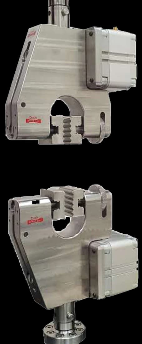
Standard 25 mm
Pneumatic Vice Action Grip
Constant air pressure across the full jaw face — enough to hold a film without cutting it at the clamp line, and identical from specimen to specimen.
Specifications
Testing standard
Plastics — Determination of tensile properties — Part 3: Test conditions for films and sheets
Written and technically reviewed by Dak System Inc. engineeringLast reviewed
ISO 527-3 is the tensile test for plastic films and sheets below 1 mm thick. A plain rectangular strip with no waisting is pulled apart at constant speed, and results are reported separately for the machine direction and the transverse direction — because film is anisotropic and a single figure does not describe it.
From the test method to your testing system
Explore the DAK machines already listed for ISO 527-3, then review the grips, measurement and setup requirements below.
 Universal Testing MachineSeries 7200Explore the machine →
 Universal Testing MachineSeries 9000Explore the machine →
01Understand the method
A rectangular strip of film or thin sheet is clamped at both ends between flat jaws, with no waisting anywhere along its length. The crosshead moves at a constant speed and pulls the strip along its own axis until it breaks. Force and extension are recorded throughout, with strain taken from an extensometer or from **gauge marks**, so the complete curve is captured rather than the breaking load alone.
The method reports tensile strength at yield and at break, elongation at yield and at break, and tensile modulus, each quoted separately for the **machine direction** and the **transverse direction**. Strength and elongation govern lot release on a converting line and decide whether a gauge can be reduced without bags splitting. Modulus feeds web-tension and stiffness calculations for winding and printing. The gap between the two directions quantifies orientation from the die or casting line, so a drifting process shows up in the numbers before it shows up in complaints.
02Prepare the specimen and test settings
A film tensile figure quoted without its direction is not usable. Machine and transverse results can differ by a large factor on an oriented film, and the drift between them is how a process problem shows up before the complaints do.
03Build the test setup on a DAK machine
Film parts at very low loads — a 25 mm strip of blown polyethylene 25 µm thick breaks well under 100 N — so a 500 N to 1 kN load cell is the working range and a single-column bench frame carries the work. The method's own envelope reaches far higher: the widest, thickest specimen it admits, a 25 mm strip of strongly oriented polyester at the full 1 mm limit, approaches 5 kN. The cell is therefore chosen for the material, not for the standard. Force indication must meet ISO 7500-1 Class 1.
Speed follows the property. Tensile modulus is run at 1 mm/min, the speed selected to give a strain rate as near as possible to 1 % of gauge length per minute; strength and elongation use a nominal speed from the ISO 527-1 series — 5, 50, 100, 200, 300 or 500 mm/min. Plastics are rate-sensitive, so the speed used is part of the result.
Strain measurement is required, not optional. The modulus chord runs between 0.05 % and 0.25 % strain over 50 mm, which demands an ISO 9513 Class 1 device, and a small **preload** to remove slack so the curve starts from zero. Elongation then runs to break: 0–50 % for oriented polyester and rigid sheet, but commonly 500 % and beyond for cast and blown polyolefin, which rules out a clip-on and calls for a **long-travel extensometer** or a **video extensometer**. Grips are parallel-closing and pneumatic at regulated low pressure, with soft rubber or line-contact faces wider than the strip; roller grips spread the clamping load for very extensible or slippery film. Serrated faces tear film.
Constant air pressure across the full jaw face — enough to hold a film without cutting it at the clamp line, and identical from specimen to specimen.
Specifications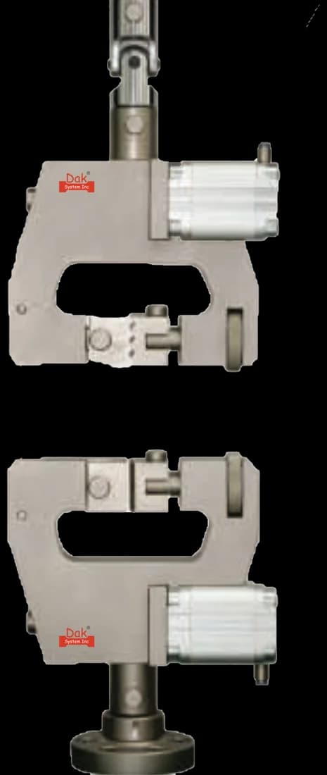
Light duty closure for delicate webs, where a heavier grip would damage the strip before the test began.
SpecificationsDak verifies against whichever standard the method names, and where a class applies our frames sit a class tighter than it asks.
| The method asks for | Dak supplies | |
|---|---|---|
| Capacity | Film breaks at very low loads — a 25 mm strip of blown polyethylene at 25 um thick parts at well under 100 N — so a 500 N to 1 kN load cell is the working range and a single-column bench frame is normally enough. The method's own envelope reaches higher: the widest, thickest specimen it admits, a 25 mm strip of a strong oriented polyester at the full 1 mm limit, could approach 5 kN, so the load cell must be chosen for the material, not the standard. | Load cells from 1 kg to 60 ton on the Series 7200, and 0.5 to 100 kN on the Series 9000 |
| Force accuracy | ISO 7500-1 Class 1 | ISO 7500-1 Class 0.5 — a class tighter than the method asks |
| Strain measurement | An extensometer to ISO 9513 Class 1 (for tensile modulus, inherited from ISO 527-1); extensometer or printed gauge marks required for all strain measurement, gauge length 50 | Certified to ISO 9513 Class 1 and ASTM E83 — non-contact video, clip-on and high-elongation |
| Gripping | Parallel-closing pneumatic film grips with rubber-faced or line-contact jaws at 100 mm separation; roller grips for highly extensible film | Our vice-action grips or self-tightening eccentric roller grips, built to the specimen |
| Environment | Condition and test in the ISO 291 standard atmosphere, 23 °C and 50 % RH, at least 16 h | 3009 series chambers, −150 °C to +400 °C — temperature only |
04Run the test
05Calculate, report and interpret
σ = F / (w × t)
Thickness is the weak link on thin gauge-variable film — measure it at several points and average, or the strength figure carries that error.
ε = ΔL₀ / L₀
From an extensometer or from gauge marks, not from grip separation.
Et = (σ2 − σ1) / (ε2 − ε1)
Jaw-line tearing is the signature failure: the clamp raises a local stress at the jaw edge and the strip parts there instead of in the gauge length, understating both strength and elongation. Slippage is the opposite error — the strip creeps out of the jaws, the curve flattens and modulus falls. A burr or nick from a blunt blade initiates the break at the edge early. Clip-on extensometers slip on thin film, so strain reads low and modulus reads high.
06Compare methods and find answers
| ISO 527-3 | ASTM D882 | |
|---|---|---|
| Specimen | Plain strip, 10 to 25 mm wide | Plain strip, commonly 25.4 mm |
| Reference length | 50 mm marked gauge | Grip separation |
| Grip separation | 100 ± 5 mm | 125, 100 or 50 mm by elongation |
| Speed basis | Nominal series | Set by expected elongation |
| Distinctive output | Modulus as a fixed-interval chord | Breaking factor, N/mm width |
| Direction | Both, reported separately | Reported, both recommended |
Both cover film and neither converts to the other. The reference length is the difference most likely to be overlooked: ISO strains against a marked 50 mm gauge, ASTM against the grip separation, so the same strip yields two different elongation figures.
It is the part of the ISO 527 series covering tensile properties of plastic films and sheets below 1 mm thick. A plain rectangular strip with no waisting is pulled apart at constant speed, and the method reports strength and elongation at yield and at break, and tensile modulus, separately for each principal direction.
Because a waisted shoulder would force the break to a chosen point rather than letting the film fail at its genuinely weakest section. On thin film the waist also becomes a stress concentration in its own right. The plain strip lets the material decide where it fails, which is what the test is trying to find out.
Because blown and cast films are oriented by the process, so machine-direction and transverse-direction properties differ — sometimes by a large factor. A single figure does not describe the film. The gap between the two is itself useful: a drifting ratio flags a process change before it produces field complaints.
Both cover film and they are not interchangeable. The one most often overlooked is the reference length: ISO strains against a marked 50 mm gauge while ASTM strains against the grip separation, so the same strip gives two different elongation figures. ASTM also carries breaking factor, the force-per-width figure for material whose thickness cannot be gauged reliably.
100 ± 5 mm, reducible to 50 mm where elongation is large. That is separate from the 50 mm gauge length, which is what strain is actually referred to — the two numbers are different things and both belong on the report.
Either the jaw faces bit into the film and cut it at the clamp line, or the strip was clamped out of square so one edge carried more load. Film is unforgiving here because there is no waist to draw failure away from the grips. A strip that tears at the jaw line is invalid under the method and has to be replaced.
Discuss your specimen, test requirements and reporting needs with DAK engineering.
This page describes the method as practised. The governing text is the current edition from the issuing body. Tell us what you are testing and we will answer with the machine, the fixture and a quotation.