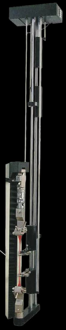
Testing standard

ISO 6259-1 / -3

Thermoplastics pipes — Determination of tensile properties — Part 1: General test method; Part 3: Polyolefin pipes

Written and technically reviewed by Dak System Inc. engineeringLast reviewed

The ISO 6259 series determines the tensile properties of thermoplastics pipes — stress at yield and elongation at break — on test pieces taken longitudinally from the pipe wall and tested at full wall thickness. Part 1 carries the general method for all thermoplastics pipe; Part 3 covers polyolefin pipe, meaning polyethylene, cross-linked polyethylene, polypropylene and polybutene. Both current editions are dated 2015.

At a glance

Test type
Tensilethe specimen is pulled apart
Published by
ISO
Edition
ISO 6259-1:2015

What the test does

Test pieces of specified shape are taken from the wall of a finished pipe in the longitudinal direction, by cutting or machining, and pulled in a tensile machine under specified conditions. Part 1 carries the general method — definitions, apparatus, sampling, conditioning and expression of results — and the material parts add what changes for that polymer family. Part 3 covers polyethylene, cross-linked polyethylene, polypropylene and polybutene. The properties determined are stress at yield and elongation at break; Part 1 applies to all thermoplastics pipe.

What it measures, and why it matters

The material as the extruder actually delivered it, in the form it will be used in. The series was drawn up on the basis of ISO 527, and Part 3's introduction says why it is separate: ISO 527 is written for sheet, with test pieces a few millimetres thick, whereas a pipe wall can exceed 50 mm and the pipe is deliberately tested as supplied, without reducing the thickness. Everything different about ISO 6259 follows from that.

Yield stress from a pipe wall is a process check as much as a material check — it responds to the compound, to how the melt was cooled and to degradation in the extruder. Elongation at break on a polyolefin separates a sound pipe from an embrittled one, and is often the figure a product standard sets a minimum against. Neither substitutes for long-term performance: the standard says plainly that the results serve as a material or process control test and are not a quantitative assessment of long-term pipe behaviour, which is the province of internal-pressure, creep and fatigue testing.

Test pieces and how they are taken

The pipe is tested as supplied, without reducing the wall thickness. Everything that separates ISO 6259 from ISO 527 follows from that one decision — a pipe wall can exceed 50 mm where ISO 527 assumes a few millimetres of sheet.

Orientation
Taken from the pipe in the longitudinal direction
Preparation
By die cutting or machiningPart 3: at 12 mm wall and below the test pieces are preferably die cut; above 12 mm they are preferably machined.
Thickness
That of the pipe — the full wall is retained
Type 1
150 mm long minimum, 20 mm ends, 10 mm narrow portion, 50 mm gaugeIdentical to the Type 1B test piece of ISO 527-2. Narrow parallel-sided portion 60 mm, initial grip separation 115 mm.
Type 2
115 mm long minimum, 25 mm ends, 6 mm narrow portion, 25 mm gaugeIdentical to the Type 2 test piece of ISO 6259-2, the PVC part of the series.
Type 3
The Type B test piece of ISO 13953The thick-wall geometry, shared with the butt-fusion joint method. This is the direct link between the two standards.
Choice of type
Dependent on the wall thickness of the pipe it came from
Widening the ends against slippage
Recommended in proportion to wall thicknessPart 3 recommends increasing the width of the ends as the wall thickness rises, precisely because a thick, tough test piece slips or breaks at the grip before it yields in the gauge.
Avoid damaging the piece when die cutting
The standard warns against damage and against producing non-parallel sides — the two things a die does to a wall it is too thick for.
Do not let machining heat the test face
DakA polyolefin surface that has been smeared or annealed by a blunt cutter is no longer the material the extruder delivered.

Quoting a figure without naming the part and the test piece type it came from makes it uninterpretable. Three geometries with different gauge lengths sit under one series designation, and an elongation at break is only meaningful against the gauge it was measured over.


Test speed and conditions

Speed is not a free choice and is not one number. It follows from the constituent material and the wall thickness, and is set by the relevant material part rather than by the operator.

Speed
From the relevant part of ISO 6259 for that material and wall thickness
Properties determined
Stress at yield, and elongation at breakPart 2, the PVC part, additionally covers stress at break.
Pre-stressing
Permitted, to obtain correct alignment and seatingPart 1 allows it to avoid an irregularity at the start of the stress–strain diagram.
Report the part, the type and the speed together
DakAll three change the number. A result carrying only the series designation cannot be reproduced by anyone else.

Calculations

Both reported properties come from the initial dimensions of the test piece and the marked gauge length, not from anything measured after the specimen has drawn.

Initial cross-sectionA

A = b × h

A
initial cross-section, mm²
b
width — the larger initial dimension of the rectangular section in the central part, mm
h
thickness — the smaller initial dimension of that section, and for pipe the wall thickness, mm

Defined in Part 1 as the product of initial width and thickness. Everything downstream uses this area.

Stress at yieldσy

σy = F / A

σy
stress at yield, MPa
F
force measured at yield, N
A
initial cross-section, mm²

Yield is defined as the transition from elastic to plastic deformation, usually shown by a decrease or a shoulder in the stress–strain curve.

Elongation at breakεb

εb = (L − L₀) / L₀ × 100

εb
elongation at break, %
L
gauge length at break — the distance between the gauge marks on the central part at break, mm
L₀
initial gauge length between those marks, mm

Calculated from the gauge length at break, so it belongs to the marked gauge and not to the distance between the grips.

How the test runs

  1. 01Sample the pipe as the product standard specifies.
  2. 02Take test pieces longitudinally from the wall by die cutting or machining, choosing the route by wall thickness.
  3. 03Select the test piece type for that wall thickness, and widen the ends in proportion where slippage is a risk.
  4. 04Keep the full wall thickness — the pipe is tested as supplied.
  5. 05Measure width and thickness in the central part and compute the initial cross-section.
  6. 06Mark the gauge length on the central part.
  7. 07Condition as the relevant part requires, and test in the same conditions.
  8. 08Set the grips so the major axis of the test piece lies on the direction of pull through the centreline.
  9. 09Clamp so that slip is prevented as far as possible, without causing premature fracture at the grips.
  10. 10Pre-stress lightly if needed to settle the piece and remove the toe from the curve.
  11. 11Fit a long-travel or non-contact extensometer where elongation at break is required on polyolefin.
  12. 12Pull at the speed set by the relevant part for that material and wall thickness.
  13. 13Record force against extension through yield to break.
  14. 14Compute stress at yield on the initial cross-section, and elongation at break from the gauge length at break.
  15. 15Report the mean, naming the part, the test piece type and the speed.

A break at the grip is the dominant failure on a thick, tough polyolefin test piece, and the instinctive fix — tightening the jaws — makes it worse. The standard's own answer is to widen the ends in proportion to the wall thickness.

Grips and fixtures for this method

Universal parallel wedge grips holding a flat specimen between self-tightening jaws
Self-tighteningTJ-15

Universal Parallel Wedge Grips

Part 1 requires a grip that maintains or increases pressure on the test piece as the force rises — a description of self-tightening wedge action. Sliding wedges do exactly that, and hold a thin-wall test piece without the operator having to guess at a clamping force. Thicker walls need jaw faces built to the section.

Specifications
High elongation long stroke extensometer
800 mm travel

High Elongation Extensometer

Polyolefin pipe elongates enormously before it breaks and a clip-on gauge runs out of stroke long before the test does. The adjustable 15 to 50 mm gauge covers the 50 mm gauge of the Type 1 test piece, and the gripper arms release at break rather than being dragged into the failure.

Specifications

What the report has to contain

  • Reference to ISO 6259 and the part used, with the edition
  • Full identification of the pipe — material, designation, nominal size and wall thickness
  • Where in the pipe the test pieces were taken
  • Test piece type, and whether die cut or machined
  • Measured width and thickness, and the initial cross-section used
  • Initial gauge length
  • Conditioning and the test temperature
  • Speed of testing
  • How elongation was measured
  • Stress at yield for each test piece
  • Elongation at break for each test piece
  • Number of test pieces, the mean, and any test piece rejected with the reason

What the machine must be capable of

A tensile machine complying with ISO 5893, the specification for constant-rate-of-traverse rubber and plastics test equipment. The load indicator must be essentially free from inertia lag at the rate used and indicate load to within 1 % of the actual value. ISO 5893 is the normative requirement here; ISO 7500-1 is drawn to the reader's attention rather than imposed.

The grip requirement is written as behaviour, not as a part number. Grips must hold the test piece so its major axis coincides with the direction of pull through the centreline, prevent slip as far as possible, and be of a type that maintains or increases pressure as the force rises — a description of a self-tightening wedge or a vice action closed under pressure. The clamping system must not cause premature fracture at the grips, and pre-stressing to settle the test piece is permitted.

Test speed depends on the constituent material and the wall thickness, and comes from the relevant part rather than being chosen. Polyolefin pipe elongates enormously before breaking, so elongation at break needs a long-travel or non-contact device; a clip-on gauge runs out of stroke first.

What goes wrong in practice

Grip breaks, the dominant failure on a thick, tough test piece, usually solved by widening the ends rather than tightening the jaws. Die cutting a wall that should have been machined, leaving non-parallel sides and a low result. Machining that heats the face being tested. Taking elongation from crosshead travel, which includes slip and machine compliance. And quoting a figure without saying which part and test piece type produced it.

Where ISO 6259 sits among the pipe and plastics tensile methods

All four pull a polymer in tension. Only one of them tests the pipe wall at full thickness, and only one of them tests across a fused joint.

ISO 6259-1 / -3ISO 527-1 / -2ISO 13953ASTM D638
SubjectThermoplastics pipe, as suppliedPlastics in sheet or moulded formA butt-fused PE jointRigid and semi-rigid plastics
SpecimenTaken longitudinally from the pipe wall, full thicknessMoulded or machined dumbbells a few millimetres thickWaisted piece machined across the jointFive dumbbell types
ReportsStress at yield, elongation at breakThe full tensile property set including modulusTensile strength and ductile-or-brittle failure modeStrength at yield and break, elongation, modulus
AnswersWas the pipe extruded from sound materialHow does the material rankWas the fusion soundHow does the grade rank

ISO 6259 exists because ISO 527's geometries do not suit pipe, and the two are not interchangeable on a certificate. ASTM D638 is a different method again and is not an equivalent — a supplier certifying to one and a customer testing to another will disagree on a compliant material.

Questions we are asked about this test

What is ISO 6259?

It is the ISO series for determining the tensile properties of thermoplastics pipes — stress at yield and elongation at break. Part 1 is the general test method and applies to all types of thermoplastics pipe regardless of intended use; Part 2 covers the PVC family and Part 3 covers polyolefin pipe. Test pieces are taken longitudinally from the pipe wall and tested at the full wall thickness.

What is the current edition of ISO 6259-1 and ISO 6259-3?

ISO 6259-1:2015 and ISO 6259-3:2015, both second editions, both published in 2015 and both confirmed as current on the ISO catalogue. Each cancelled and replaced its 1997 first edition after technical revision, and those 1997 editions are withdrawn. Part 2 is ISO 6259-2:2020. The series is maintained by ISO/TC 138/SC 5.

Why not just use ISO 527?

Because ISO 527 is written for materials in sheet form with test pieces a few millimetres thick, and a pipe wall can exceed 50 mm. ISO 6259 was drawn up on the basis of ISO 527 but takes the deliberate decision to test the pipe as supplied, without reducing the thickness, and the different test piece geometries follow from that. For greater detail on the underlying principles the series points the reader back to ISO 527.

Which materials does Part 3 cover?

Polyolefin pipes: polyethylene, cross-linked polyethylene, polypropylene and polybutene. It determines stress at yield and elongation at break, and carries the corresponding basic specifications in informative annexes for information purposes only.

Which test piece type should I use?

The choice depends on the wall thickness of the pipe the piece was taken from. Type 1 is the ISO 527-2 Type 1B geometry, 150 mm long with a 10 mm narrow portion and a 50 mm gauge. Type 2 is the smaller geometry shared with the PVC part. Type 3 is the Type B test piece of ISO 13953, the thick-wall geometry. Below about 12 mm of wall the piece is preferably die cut; above it, machined.

What machine does ISO 6259 require?

A tensile machine complying with ISO 5893, the specification for constant-rate-of-traverse rubber and plastics test equipment, with a load indicator essentially free from inertia lag at the rate used and indicating load to within 1 % of the actual value. ISO 5893 is the normative requirement; Part 1 draws attention to ISO 7500-1 rather than imposing it. Computer-controlled machines in accordance with ISO 527-1 are an option.

What grips does the method specify?

It describes behaviour rather than a part number. The grips must hold the test piece so its major axis coincides with the direction of pull through the centreline, prevent slip as far as possible, and be of a type that maintains or increases pressure as the applied force rises — which describes a self-tightening wedge or a vice action closed under pressure. The clamping system must not cause premature fracture at the grips.

Why does my test piece keep breaking at the grip?

Almost always because the wall is thick and tough enough that the clamped ends reach their limit before the gauge section yields. The standard's own remedy is to increase the width of the ends in proportion to the wall thickness, not to tighten the jaws — extra clamping force on a polyolefin simply moves the damage forward. Non-parallel sides left by a die used on too thick a wall have the same effect.

Can ISO 6259 results predict how long a pipe will last?

No, and the standard says so directly. The results are principally a test of the material in the form of pipe and can be useful as a material or process control test, but they are not a quantitative assessment of long-term pipe performance. Applications where the conditions of force application differ considerably need the appropriate impact, creep and fatigue tests instead.

How does ISO 6259 relate to ISO 13953?

Directly, and by design. ISO 13953 determines the tensile strength and failure mode of a test piece taken across a butt-fused polyethylene joint, and its Type B test piece is the same geometry as the Type 3 test piece of ISO 6259-3. One measures the pipe material, the other measures the joint made in it, and a pipeline specification frequently calls for both.

Running ISO 6259-1 / -3 on the Series 7200 and Series 9000

Dak verifies against whichever standard the method names, and where a class applies our frames sit a class tighter than it asks.

The method asks forDak supplies
CapacitySet by the test piece section, which carries the full wall thickness — modest on a thin-walled Type 2 piece and substantial on a thick-wall Type 3. Size the frame from the wall area and the material, not from the pipe diameter.Load cells from 1 kg to 60 ton on the Series 7200, and 0.5 to 100 kN on the Series 9000
Force accuracyISO 5893; the load indicator shall be essentially free from inertia lag at the rate used and indicate load to within 1 % of the actual value. ISO 7500-1 is drawn to the reader's attention in Part 1, not imposedISO 7500-1 Class 0.5 — a class tighter than the method asks
Strain measurementAn extensometer to not specified — Part 1 assigns no extensometer class; elongation at break is calculated from the gauge length at break, so the device must follow the marked gauge and not the grips, gauge length 50 (Type 1); 25 (Type 2); Type 3 is the ISO 13953 Type B geometryCertified to ISO 9513 Class 1 and ASTM E83 non-contact video, clip-on and high-elongation
GrippingGrips that keep the major axis of the test piece on the direction of pull, prevent slip as far as possible, and maintain or increase pressure as the force risesOur self-tightening serrated wedge grips, with V-jaws for round specimens or vice-action grips, built to the specimen
EnvironmentConditioning as the relevant part requires, with the test run in the same conditions3009 series chambers, −150 °C to +400 °C — temperature only

This page describes the method as practised. The governing text is the current edition from the issuing body. Tell us what you are testing and we will answer with the machine, the fixture and a quotation.

Materials tested to it

The test it standardises

Other standards explained