Testing standard

ISO 8510-2

Adhesives — Peel test for a flexible-bonded-to-rigid test specimen assembly — Part 2: 180° peel

Written and technically reviewed by Dak System Inc. engineeringLast reviewed

ISO 8510-2 peels a flexible adherend off a rigid one by folding it back through 180° and pulling. Because one adherend is rigid the peel angle is genuinely controlled, which is the difference between this method and a T-peel where the specimen chooses its own angle.

At a glance

Test type
Peel & adhesiona bonded joint is pulled apart
Published by
ISO
Edition
ISO 8510-2:2006

What the test does

A flexible adherend is bonded to a rigid one over a defined length, with an unbonded tab left at one end. After curing and conditioning, the rigid adherend is mounted in a fixture that holds the geometry, the flexible tab is folded back through 180° and gripped, and the assembly is pulled at a substantially steady rate so the bond separates progressively. The force over the steady portion of the peel — excluding the higher force required to start it — is averaged and divided by the bonded width to give a peel resistance in force per unit width.

What it measures, and why it matters

The resistance of a bond to a crack running along it at a controlled angle. The control is the point. Because one adherend is rigid it cannot move aside, so 180° stays 180° for the whole of the peel, and the result is a property of the bond at a stated geometry rather than at a geometry the specimen chose. This matters because peel resistance genuinely depends on angle: part of the measured force goes into bending the flexible adherend, and that share changes with the angle. There is no conversion between 180°, 90° and T-peel values, which is why the series is split into parts.

Why the angle is fixed

A rigid adherend holds the geometry, so 180° means 180°. That is the whole reason this method exists beside the T-peel.

Adherends
One flexible, one rigid
Angle
180° — the flexible strip folded back on itselfControlled, because the rigid adherend cannot move out of the way.
Part 1
Covers 90° peel on the same specimen typePeel resistance changes with angle, so the two parts give different numbers for the same bond.
Result
Average force per unit width over the peel
Rigid adherend support
Held so the angle does not driftA travelling support or a suitable fixture; a plain grip lets the rigid part rotate as the crack advances.
Watch for the flexible adherend breaking
Rather than the bondDakIf the strip breaks first the bond was stronger than the adherend, and there is no peel value to report.

Peel resistance is a function of angle. Quoting a peel value without the angle and the method is quoting a number that cannot be checked against anything.

Test speed

Rate
Substantially steady, as specified
Reported
Average peel force per unit width
Averaging
Over the steady portion, excluding start-up
Keep the trace
Stick-slip does not survive averagingDak

Calculations

Peel resistance

Average force over the steady peel, divided by the bonded width

force
mean force over the averaging length, N
width
bonded width, mm

Force per unit width, commonly N/mm, and only comparable against results at the same angle.

Angle dependence

Peel resistance at 180° is not convertible to 90° or to a T-peel value

There is no general conversion. The energy going into bending the flexible adherend changes with angle, and it is not separable from the bond's own contribution.

How the test runs

  1. 01Bond a flexible adherend to a rigid one over the specified length, leaving an unbonded tab.
  2. 02Cure and condition the assemblies.
  3. 03Measure the bonded width.
  4. 04Mount the rigid adherend in a fixture that holds the peel angle constant.
  5. 05Fold the flexible tab back through 180° and grip it.
  6. 06Select a load cell suited to a few tens of newtons.
  7. 07Pull at the specified steady rate.
  8. 08Peel far enough past the start-up transient to establish a steady trace.
  9. 09Average the force over the steady portion and divide by the bonded width.
  10. 10Record whether failure was cohesive, adhesive, or the flexible adherend breaking.
  11. 11Report the angle, the method and the averaging length with the value.

The fixture this method needs

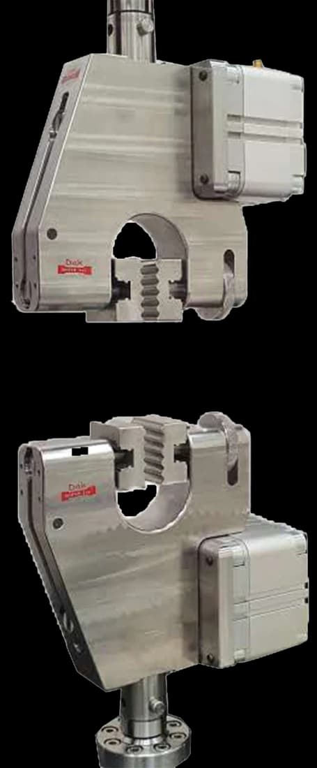
Pneumatic vice action grips with 25 mm square jaw faces
Standard 25 mm

Pneumatic Vice Action Grip

Pneumatic vice action grips hold each arm of the T at a constant pressure through a long peel, which a screw grip does not — a peel test runs for hundreds of millimetres and a slipping grip corrupts the whole trace.

Specifications

What the report has to contain

  • Reference to ISO 8510-2 and the edition
  • Adhesive identification and batch
  • Flexible and rigid adherend materials, thicknesses and surface treatments
  • Bonded width and length
  • Cure schedule and conditioning
  • Rate of traverse
  • Length over which the force was averaged
  • Average peel force per unit width
  • Failure mode, including any adherend failure
  • How the rigid adherend was supported

What the machine must be capable of

Small forces and long travel. Peel forces here commonly sit between a few newtons and a few tens of newtons, so the load cell is chosen for that range — an accuracy class applies only down to a stated fraction of capacity, and below it the class stops describing the instrument. The peel runs for a considerable distance, so the grip on the flexible strip must hold without creeping for the whole of it, and the fixture holding the rigid adherend must maintain the angle throughout rather than only at the start.

What goes wrong in practice

Clamping the rigid adherend in a plain grip, so the angle drifts during the test. Averaging over too short a peel, so the start-up transient dominates and the result describes how the tab was made. Quoting a peel value without its angle and method, which makes it uncheckable — a common failing in supplier data. Reporting an adherend break as a peel resistance. And discarding the trace, which is where stick-slip lives and where the average cannot show it.

ISO 8510-2 or ISO 11339

ISO 8510-2ISO 11339
AdherendsOne flexible, one rigidBoth flexible
Angle180°, controlledWhatever the specimen adopts
Comparable with each otherNoNo
Also seeISO 8510-1 for 90°ASTM D1876

Different geometries answering the same question about the same adhesive, and they will not give the same number. Choose by what the real joint looks like: a flexible layer on a rigid substrate is this one.

Questions we are asked about this test

What is ISO 8510-2?

It is Part 2 of the ISO 8510 peel series, covering the 180° peel of an assembly where one adherend is flexible and the other rigid. The flexible strip is folded back on itself and pulled, so the bond separates progressively, and the average force over the steady portion of the peel is divided by the bonded width. The current edition is ISO 8510-2:2006, adopted in Europe as EN ISO 8510-2:2010.

How is this different from a T-peel?

The angle. Here one adherend is rigid, so it cannot move out of the way and the 180° geometry is genuinely maintained as the crack front travels. In a T-peel both adherends are flexible and the specimen adopts whatever angle the balance of forces produces. That makes this method the right one when the real joint is a flexible layer bonded to a rigid substrate, and it means the two sets of results are not comparable with each other.

Can a 180° peel value be converted to a 90° one?

No. Peel resistance depends on angle because part of the measured force goes into bending the flexible adherend rather than into breaking the bond, and that share changes with the angle. There is no general conversion between them, which is why ISO 8510 has separate parts for 90° and 180° and why a peel value quoted without its angle and method cannot be checked against anything.

Why does the rigid adherend need a proper fixture?

Because if it is simply clamped it will rotate as the crack advances, and the peel angle drifts away from 180° during the test. Since the result depends on the angle, a drifting angle means the number is an average over a geometry that changed while it was being measured. A travelling support or a fixture designed for the purpose keeps the angle where the method says it should be.

What if the flexible adherend breaks instead of the bond?

Then there is no peel value. It means the bond was stronger than the flexible adherend, which is useful information about the joint but is not the measurement the method makes. It should be recorded as an adherend failure rather than reported as a peel resistance, and if the intention was to characterise the adhesive, a stronger or thicker flexible adherend is needed.

Why is the start-up part of the peel excluded?

Because initiating a peel takes more force than continuing one, and the extra depends on how the unbonded tab was formed rather than on the adhesive. Averaging only the steady portion, after peeling far enough to get past that transient, describes the running resistance of the bond. The averaging length is reported for the same reason: it is part of what produced the number.

Why keep the force trace?

Because a smooth peel and a stick-slip peel can average to exactly the same value. A saw-toothed trace means the crack repeatedly arrested and jumped forward, which is characteristic of a brittle bond line and behaves quite differently in service from a bond that separates steadily. Once reduced to a mean, that distinction is gone.


Running ISO 8510-2 on the Series 7200 and Series 9000

Dak verifies against whichever standard the method names, and where a class applies our frames sit a class tighter than it asks.

The method asks forDak supplies
CapacityVery low — 180° peel forces are commonly a few newtons to a few tens of newtonsLoad cells from 1 kg to 60 ton on the Series 7200, and 0.5 to 100 kN on the Series 9000
Force accuracyISO 7500-1 Class 1 at the actual peel forceISO 7500-1 Class 0.5 — a class tighter than the method asks
GrippingA grip for the flexible adherend and a fixture holding the rigid one so the peel stays at 180°Our peel and adhesion fixtures, built to the specimen
Environment23 ± 2 °C standard laboratory atmosphere3009 series chambers, −150 °C to +400 °C — temperature only

This page describes the method as practised. The governing text is the current edition from the issuing body. Tell us what you are testing and we will answer with the machine, the fixture and a quotation.

Materials tested to it

The test it standardises

Other standards explained