
5 to 400 kNTJ-125
Direct Compression Fixture
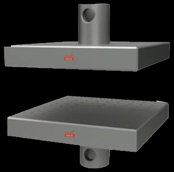
Flat, parallel platens. On a sandwich coupon the platens must stay parallel as load rises, or one facing takes the load before the other.
Specifications
Testing standard
Edgewise compressive strength of corrugated fiberboard (short column test)
Written and technically reviewed by Dak System Inc. engineeringLast reviewed
TAPPI T 811 determines the edgewise compressive strength of a short column of single-, double- or triple-wall corrugated fibreboard, loaded parallel to the flutes. It is the edge crush test that box compression is predicted from.
From the test method to your testing system
Explore the DAK machines already listed for TAPPI T 811, then review the grips, measurement and setup requirements below.
 Universal Testing MachineSeries 7200Explore the machine →
 Universal Testing MachineSeries 9000Explore the machine →
01Understand the method
A short column of conditioned corrugated board is cut square, its loaded edges prepared as the method requires, and stood between flat parallel platens with the flutes running vertically. It is compressed until it fails, and the maximum force is divided by the specimen width to give the edgewise compressive strength. Two loading procedures are permitted and each has its own figure. On a rigid-support machine the driven platen runs at 12.5 ± 0.25 mm/min (0.5 ± 0.01 in./min). On a flexible-beam machine the platen is driven so that force rises at 111 ± 22 N/s (25 ± 5 lbf/s), which on most such machines works out at 13 to 51 mm/min (0.5 to 2.0 in./min) depending on the load range at the beam; there the rate actually used is recorded. Whichever is chosen, the guide blocks come away once the force reaches 22 to 67 N (5 to 15 lbf) and the rate is not altered afterwards. Single-, double- and triple-wall constructions are all covered.
How much load a wall of corrugated board carries on its edge, which is the property a stacked box is designed around. Corrugated board is a structure rather than a material: the flutes are slender members braced by the liners, and loading parallel to them tests exactly the mechanism that keeps a pallet standing. ECT is also the middle link in a chain — the component paper's own compressive strength governs the board's ECT, and the board's ECT governs the compression resistance of the finished box — so testing at the wrong link answers a different question.
02Prepare the specimen and test settings
The method allows constant strain rate or constant load rate, and states that either gives the same result within its precision.
ECT is the property box compression is predicted from. It is the middle link in the chain: the paper's own compressive strength governs ECT, and ECT governs how the finished box behaves under a stack.
03Build the test setup on a DAK machine
Modest force, from a few hundred newtons to a few kilonewtons, through flat platens that stay parallel as load rises. What is unusual is the latitude on rate: either 12.5 ± 0.25 mm/min of platen travel or a force rising at 111 ± 22 N/s, on the evidence that any combination of its permitted procedures yields the same result within the stated precision. That is a genuine convenience, but the procedure used and the rate run still belong in the report so a reader can see which was relied on.
Flat, parallel platens. On a sandwich coupon the platens must stay parallel as load rises, or one facing takes the load before the other.
SpecificationsDak verifies against whichever standard the method names, and where a class applies our frames sit a class tighter than it asks.
| The method asks for | Dak supplies | |
|---|---|---|
| Capacity | Low to moderate — corrugated ECT values commonly run from a few hundred newtons to a few kilonewtons | Load cells from 1 kg to 60 ton on the Series 7200, and 0.5 to 100 kN on the Series 9000 |
| Force accuracy | unknown — no accuracy class could be confirmed for this method | ISO 7500-1 Class 0.5 — the method sets no class of its own |
| Gripping | Flat parallel platens, with the specimen edges waxed or otherwise supported as the method requires | Our compression anvils, built to the specimen |
04Run the test
05Calculate, report and interpret
Maximum force divided by the specimen width
Force per unit width, commonly kN/m. Board thickness is not a usable area — the flutes are mostly air.
Paper compressive strength → board ECT → box compression
Each link is measured by a different standard, and testing at the wrong one answers a different question.
Specimens that are not standing square, which is the commonest avoidable error and leaves no trace. Unsupported edges, which move the failure to the platen. Dividing by the board caliper to produce a stress, when corrugated board is mostly air and the thickness is not a usable area. Reporting ECT without the wall construction and flute profile, which makes it uncomparable. And using an ECT figure where a box compression result was wanted, or the reverse: they are adjacent links in a chain, not the same measurement, and a formula exists to get from one to the other precisely because they are not interchangeable.
06Compare methods and find answers
| TAPPI T 811 | ISO 3037 | |
|---|---|---|
| Family | TAPPI / ANSI | ISO |
| Test | Edgewise crush, short column | Edgewise crush |
| Loading | Constant strain or constant load | As the standard specifies |
| Cite | Where the specification names it | Where the specification names it |
The same property in two families, and packaging specifications name one. Keep a data set to a single method: specimen preparation and edge support differ enough to move the number.
It is the edge crush test — the North American method for the edgewise compressive strength of corrugated fibreboard, measured on a short column loaded parallel to the flutes. It covers single-, double- and triple-wall board. The current revision is ANSI/TAPPI T 811 om-23.
Because that is the direction in which the flutes act as columns, and it is how a box wall carries a stack. Corrugated board is a structure rather than a material: the flutes are slender members braced by the liners, and their resistance to buckling in that direction is what keeps a stacked pallet standing. Loading across the flutes measures something else entirely.
Because studies referenced by the method showed that any combination of the specimen and loading procedures it permits yields the same result within the stated precision. Each still has its own figure: 12.5 ± 0.25 mm/min of platen travel on a rigid-support machine, or a force rising at 111 ± 22 N/s on a flexible beam, which on most such machines lands between 13 and 51 mm/min. That is unusual latitude for a test standard and it is evidence-based rather than a shrug — but the report should still say which procedure was used and at what rate, since a reader cannot otherwise confirm the equivalence was relied on legitimately.
Because an unsupported cut edge of corrugated board crushes locally before the specimen's body reaches its capacity. The liners buckle outward at the platen, the flutes have nothing holding them, and the failure happens where the knife cut rather than where the material is representative. Waxing the edges, or the alternative the method provides, stiffens that zone so the column fails in its middle.
It is the middle link in a three-part chain. The component paper's own compressive strength — measured by ring crush or short-span — governs the board's ECT, and the board's ECT governs the compression resistance of the finished box. Each link has its own standard, and testing at the wrong one answers a different question from the one asked.
Because the board's thickness is not a usable area. Corrugated board is mostly air: the flutes occupy the space between the liners without filling it, so dividing by the caliper would produce a stress that means nothing physically. Force per unit width, commonly kilonewtons per metre, is the quantity box compression formulae actually consume.
A specimen that is not standing square. A short column that leans even slightly puts one edge into contact first, so that edge takes the load alone and the specimen fails early. It costs nothing to check and it is invisible afterwards — a leaning specimen and a weak board produce the same low number and the same unremarkable-looking failure.
Discuss your specimen, test requirements and reporting needs with DAK engineering.
This page describes the method as practised. The governing text is the current edition from the issuing body. Tell us what you are testing and we will answer with the machine, the fixture and a quotation.