Testing standard

IS 7906

Helical Compression Springs — Part 1 Design and Calculations for Springs Made from Circular Section Wire and Bar

Written and technically reviewed by Dak System Inc. engineeringLast reviewed

IS 7906 is the Indian multi-part standard for helical compression springs. Part 1 carries the design calculations, Part 2 the specification for cold coiled springs from wire up to 17 mm, and Part 5 the specification for hot coiled springs from bar of 8 to 60 mm. Acceptance rests on a static load test, in which the spring is first compressed three times to block length and then loaded gradually to a prescribed length, and on a spring rate taken from the characteristic curve between 0.3 and 0.7 of the force at the minimum permissible test length.

At a glance

Test type
Compressionthe specimen is squeezed
Published by
IS
Edition
1997

What the test does

IS 7906 is a design and specification series with its test procedures written into the product parts. Part 1 carries the calculations and nothing else; Parts 2 and 5 carry the tolerances, the acceptance criteria and the way a spring is loaded to demonstrate them. Two measurements decide a spring: the static load test reads the axial force at a prescribed length, and the characteristic curve test finds the spring rate from the slope of force against deflection.

Which part applies depends on how the spring was made. Part 2 covers cold coiled springs from wire up to 17 mm diameter, mean coil diameter to 200 mm and unloaded length to 630 mm. Part 5 covers hot coiled springs from bar of 8 to 60 mm, hardened and tempered after coiling, outside diameter under 460 mm, unloaded length under 800 mm and a coil ratio of 3 to 12. Above a lot size of 5000, dimensional tolerances come from Part 7.

What it measures, and why it matters

The spring rate is measured over a defined band and the band is the whole point. Part 5 requires that where the rate is checked by finding the characteristic of the spring, it be done over the range 0.3 to 0.7 of the force at the minimum permissible test length. Part 2 says the same in its 1975 wording.

The standard gives its own reason. The theoretical force-deflection diagram is a straight line, but in practice the start and finish of the characteristic depart from linearity — end coils bedding in at one end, coils approaching one another at the other. Taking the rate from the middle forty percent covers the linearity with certainty. A rate measured across the full stroke is a chord through two curved regions, and it is not the spring rate.

Tolerances are applied only where they matter. The spring rate is toleranced only if it has a decisive influence on functional behaviour, and then exactly one additional spring force is toleranced alongside it.

The spring, its preparation and its tolerances

The specimen is the finished spring. What the standard controls is its own geometry rather than the machine it is tested in.

Orientation
Standing vertically, loaded in its normal direction
Pre-scragging
Compress three times in quick succession to block lengthOr to the length corresponding to the maximum permissible static stress, whichever is greater. If scragged further afterwards there should be no further change in height.
Part 2 scope
Cold coiled, wire to 17 mm, mean coil diameter to 200 mm, unloaded length to 630 mm
Part 5 scope
Hot coiled, bar 8 to 60 mm, hardened and tempered after coilingOutside diameter under 460 mm, unloaded length under 800 mm, coil ratio 3 to 12.
Lot above 5000
Dimensional tolerances come from Part 7
Squareness, ground ends
e₁ = 0.01 L₀, about 0.57°Part 5, Table 4.
Parallelism, ground ends
e₂ = 0.015 Dₑ, about 0.9°Part 5, Table 4.
Squareness, forged or rolled flattened ends
e₁ = 0.03 L₀, about 1.7°
Parallelism, forged or rolled flattened ends
e₂ = 0.025 Dₑ, about 1.5°
Cold coiled, ground faces
e₁ = 0.06 L₀ and e₂ = 0.03 DPracticePart 2, Table 2, read from a noisy scan. Treated as probable rather than confirmed until the printed page is re-read.
Bow
Half the permitted out-of-squareness toleranceAnd the maximum must occur in the middle third of the spring.
When closer tolerances are achievable
Coil ratio under 12 and slenderness ratio L₀/D under 5Outside that, squareness and parallelism are by agreement with the manufacturer.
Total turns tolerance
±0.015 nₜ as-rolled bars · ±0.012 nₜ centreless ground barsPart 5, clause 7.3.

Loading — there is no rate

IS 7906 specifies no test speed anywhere. Parts 1, 2 and 5 were all searched for one. What the standard gives instead is a sequence and a tolerance on the instrument.

Crosshead or loading rate
None specified, in any partAny millimetre-per-minute figure attributed to IS 7906 was invented elsewhere.
Before the static test
Three compressions in quick succession to block length
Approaching the reading
Gradually approach the prescribed load lengthThen read off the corresponding axial load.
Instrument error allowed
±1 percent in the load indicationThe one numeric machine requirement in the static load clause.
Spring rate band
0.3 Fₙ to 0.7 FₙFₙ is the force at the minimum permissible test length Lₙ. Equivalently 0.3 sₙ to 0.7 sₙ in deflection.
Platen flatness
Not specifiedThe standard controls the spring's end squareness and parallelism instead. No platen flatness figure should be quoted for IS 7906.
Temperature
Ordinary room temperaturePart 1: for considerably higher or lower temperatures, refer to the spring manufacturer.

Calculations

Spring rateR

R = (F₂ − F₁) / (L₁ − L₂) = ΔF / Δs

R
spring rate, N/mm
F₁, F₂
axial spring forces, N
L₁, L₂
corresponding loaded lengths, mm
s₁, s₂
corresponding deflections, mm

Taken between 0.3 Fₙ and 0.7 Fₙ. Outside that band the real characteristic is not straight, so the slope is not the spring rate.

Spring rate tolerance, as-rolled barsΔR

ΔR = ±0.065 (D/d + 1) R

D
mean coil diameter, mm
d
bar diameter, mm
D/d
the coil ratio w

Part 5, clause 7.6. Applied only where the spring rate has a decisive influence on functional behaviour, and then exactly one additional spring force is toleranced alongside it.

Spring rate tolerance, ground barsΔR

ΔR = ±0.045 (D/d + 1) R

The tighter coefficient reflects the better dimensional control of a ground bar.

Block length, springs from as-rolled barsLc

Lc ≤ (nₜ − 0.3) d

nₜ
total number of turns, to one decimal place
d
bar diameter, mm

From ground bars, Lc ≤ (nₜ − 0.4) d_max. Other end forms have their own expressions in Part 5, clause 7.7.

Spring force toleranceΔF

±0.015 for rolled-surface rods, ±0.012 for machined-surface rods

applied to an expression in (L₀ + s), the coil ratio and the spring rate

The two coefficients and the rolled-versus-machined split are confirmed; the exact algebraic grouping was garbled in the source text layer and is not reproduced.

How a static load test runs

  1. 01Establish which part applies — Part 2 for a cold coiled spring from wire up to 17 mm, Part 5 for a hot coiled spring from bar of 8 to 60 mm.
  2. 02Confirm the proportion of springs to be tested, which the purchase order or data sheet specifies.
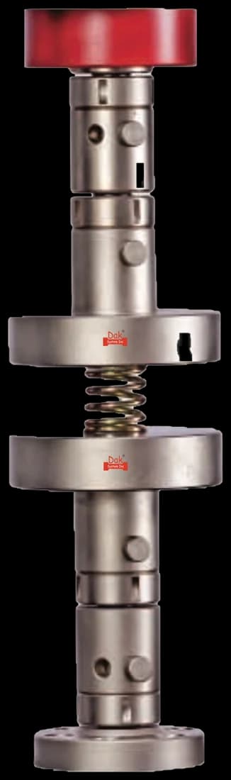
  3. 03Stand the spring vertically in its normal direction of loading, with a guide if it is slender enough to buckle.
  4. 04Compress it three times in quick succession to block length, or to the length corresponding to the maximum permissible static stress, whichever is greater.
  5. 05Check that further scragging produces no further change in height.
  6. 06Gradually approach the prescribed load length.
  7. 07Read the corresponding axial load, allowing ±1 percent instrument error.
  8. 08Where the spring rate is required, take force and deflection readings between 0.3 and 0.7 of the force at the minimum permissible test length.
  9. 09Calculate the rate from the two points and compare it with the tolerance, if one was specified.
  10. 10Check squareness, parallelism and bow against the tolerances for the end form.

Do not measure the spring rate across the full stroke. The characteristic departs from linearity at both ends — end coils bedding in at one, coils approaching one another at the other — and a slope taken through those regions is not the spring rate. The 0.3 to 0.7 band exists to cover the linearity with certainty, and the standard says so in those words.

Grips and fixtures for this method

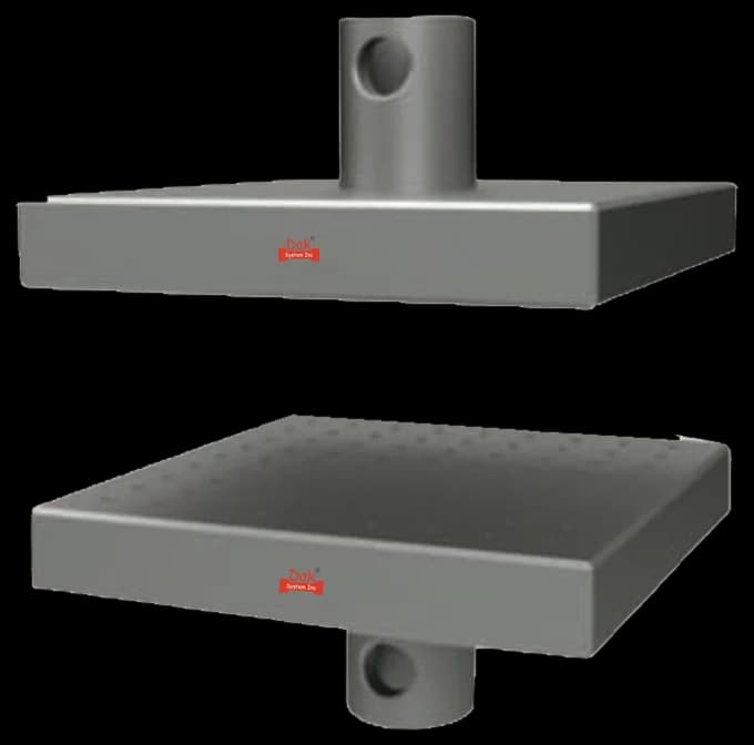
Direct compression fixture platens
5 to 400 kNTJ-125

Direct Compression Fixture

Direct compression platens with the spring standing vertically. The standard sets no platen flatness figure, controlling the spring's end squareness and parallelism instead, so what matters on the machine is that the platens stay parallel and the spring stays on axis.

Specifications
Flat-plate compression anvils, upper and lower
Rigidly fixedTJ-146

Compression Anvils

Hardened parallel anvils for smaller cold coiled springs. Any spring with a slenderness ratio above five needs a guide or cage, since the standard itself notes that closer squareness and parallelism are only achievable below that.

Specifications

What the report has to carry

  • Reference to IS 7906 and the part applied
  • Whether the spring is cold or hot coiled, and its end form
  • Bar or wire diameter, mean coil diameter and coil ratio
  • Unloaded length and total number of turns
  • Prescribed load length and the axial load measured at it
  • Spring rate, and the two force-deflection points it was taken from within the 0.3 to 0.7 band
  • Confirmation that the spring was compressed three times to block length before test
  • Squareness, parallelism and bow against the tolerance for the end form
  • Any tolerance specified on rate or force, and whether it was met
  • Proportion of the lot tested, as specified in the purchase order

What the machine must be capable of

IS 7906 specifies no test speed. There is no crosshead rate and no loading rate anywhere in Parts 1, 2 or 5. What it gives instead is a procedure and one instrument requirement: gradually approach the prescribed load length and read the corresponding axial load, with an instrument error of ±1 percent in the load indication allowed. Any millimetre-per-minute figure attributed to IS 7906 was invented somewhere along the way.

The standard likewise sets no platen flatness tolerance, controlling the spring's end geometry instead of the machine's platens.

Force capacity follows from the spring. Hot coiled bar up to 60 mm in automotive and rail suspension service reaches high loads, so the machine is chosen from the springs in the programme. A compression cage or guide is needed for any spring slender enough to buckle, since Part 2 notes closer squareness and parallelism are only achievable where the slenderness ratio is under five.

What goes wrong in practice

The spring rate band is the error that matters, and one version circulates widely: that the rate is measured between twenty and eighty percent of the working range. It is not. Both Part 2 and Part 5 say 0.3 to 0.7 of the force at the minimum permissible test length. A wider band pulls the non-linear ends into the slope and reports a rate the spring does not have.

Skipping the pre-scragging is the second. Three compressions to block length are part of the method, and omitting them means measuring a spring that has not yet settled.

The third is checking solid height as routine. The standard says it may not be specified as a rule and in the normal case is not to be checked — it becomes a requirement only when the application demands it, and then only as a maximum.

Which part do I need

PartCoversApplies to
Part 1 : 1997Design and calculationsAny helical compression spring from circular wire or bar, cold or hot coiled, at room temperature
Part 2 : 1975Cold coiled springs — specificationWire up to 17 mm, mean coil diameter to 200 mm, unloaded length to 630 mm
Part 5 : 2004Hot coiled springs — specificationBar 8 to 60 mm, hardened and tempered after coiling, outside diameter under 460 mm, coil ratio 3 to 12
Part 7Dimensional tolerancesLots exceeding 5000

Part 1 supplies the calculations that Parts 2 and 5 assume, so a specification part is not usable on its own. The committee also changed between them — Part 1 sits with the Springs Sectional Committee and Part 5 with the Automotive Springs and Suspension Sectional Committee.

End form and what it costs you

Part 5, Table 4. Ground ends buy tighter geometry, and the tolerances say by how much.

Forged or rolled flattened endsGround ends
Squareness e₁0.03 L₀ (about 1.7°)0.01 L₀ (about 0.57°)
Parallelism e₂0.025 Dₑ (about 1.5°)0.015 Dₑ (about 0.9°)
Rate tolerance coefficient±0.065 (D/d + 1) R±0.045 (D/d + 1) R
Total turns tolerance±0.015 nₜ±0.012 nₜ

A spring out of square loads its platen on one side, which both biases the force reading and encourages buckling. That is why the standard tolerances the spring's ends and says nothing at all about platen flatness.

Questions we are asked about this test

What is IS 7906?

It is the Indian Standard series for helical compression springs. Part 1 covers design and calculations for springs made from circular section wire and bar. Part 2 specifies cold coiled springs and Part 5 hot coiled springs, each with their own scope, tolerances and test procedures. Part 7 carries dimensional tolerances for large lots.

Over what range is the spring rate measured?

Between 0.3 and 0.7 of the force at the minimum permissible test length — the middle forty percent of the working range. Both Part 5 clause 10.2 and Part 2 clause 7.2 say so, and Part 5's characteristic curve figure is labelled 0.3 Fₙ and 0.7 Fₙ on the force axis and 0.3 sₙ and 0.7 sₙ on the deflection axis.

Is the spring rate band 20 percent to 80 percent?

No. That figure circulates but appears nowhere in IS 7906. The standard says 0.3 to 0.7 of the force at the minimum permissible test length, in two separate parts and in two separate decades of wording. Measuring over a wider band drags the non-linear ends of the characteristic into the slope and reports a rate the spring does not have.

Why is the rate not measured across the full stroke?

Because the real characteristic is not straight at either end. The standard explains it directly: the theoretical force-deflection diagram of a cylindrical helical compression spring is a straight line, but in practice the start and finish depart from linearity, as end coils bed in at one end and coils approach one another at the other. The 0.3 to 0.7 band is chosen so that the linearity is covered with certainty.

What speed does IS 7906 specify?

None. There is no crosshead rate and no loading rate in Part 1, Part 2 or Part 5. What the standard prescribes instead is a sequence: compress the spring three times in quick succession to block length, or to the length corresponding to the maximum permissible static stress if that is greater, then gradually approach the prescribed load length and read off the axial load. An instrument error of ±1 percent in the load indication is allowed. Any millimetre-per-minute figure attributed to IS 7906 has been invented.

Why must the spring be compressed three times before testing?

Because an unscragged spring has not yet taken its permanent set. The first few compressions to block length settle it, and the standard asks that after them further scragging produces no further change in height. A force read before that settling has happened describes a spring that will not exist after the first few working cycles in service.

Does IS 7906 set a platen flatness tolerance?

No, and it is worth knowing that it does not, because the question comes up constantly. The standard controls the geometry of the spring rather than of the machine — squareness of the ends to 0.01 of the unloaded length for a ground-ended hot coiled spring, parallelism to 0.015 of the outside diameter, and bow to half the out-of-squareness tolerance within the middle third of the spring. Do not quote a platen flatness figure for IS 7906.

Do I need to check the solid height?

Normally no. Part 5 states that the solid height may not be specified as a rule on the spring drawing, and that in the normal case it is not to be checked. It becomes a requirement only where the application depends on it, and then it is specified as a maximum value.

How does IS 7906 compare with EN 13906-1 and DIN 2095?

They occupy the same ground in different jurisdictions. EN 13906-1 is the European design standard for helical compression springs, and DIN 2095 and DIN 2096 the German specification pair for cold and hot coiled springs respectively — a split that mirrors the Part 2 and Part 5 division in IS 7906. ASTM A125 covers heat-treated helical steel springs but ASTM now records it as historical rather than active. The detailed technical differences were not verified and none are asserted here.

Part 1 supplies the calculations Parts 2 and 5 assume, so a specification part is not usable without it. Part 7 carries dimensional tolerances for lots above 5000. EN 13906-1 is the European design standard for helical compression springs, and DIN 2095 and DIN 2096 the German pair for cold and hot coiled springs. ASTM A125 covers heat-treated helical steel springs, though ASTM records it as historical. IS 4454 specifies the steel wire cold coiled springs are made from.

Running IS 7906 on the Series 7200 and Series 9000

Dak verifies against whichever standard the method names, and where a class applies our frames sit a class tighter than it asks.

The method asks forDak supplies
CapacityFollows from the spring. Hot coiled bar up to 60 mm in automotive and rail suspension service reaches high loads, so the machine is chosen from the springs in the programme rather than from the standard.Load cells from 1 kg to 60 ton on the Series 7200, and 0.5 to 100 kN on the Series 9000
Force accuracynone stated as a class, but an instrument error of plus or minus 1 percent in the load indication is expressly allowed for the static load testISO 7500-1 Class 0.5, verified to ASTM E4, DIN 51221 and BS 1610
GrippingParallel compression platens with the spring standing vertically, plus a guide or cage for any spring slender enough to buckle. The standard tolerances the spring end geometry rather than the platens and sets no platen flatness figure.Our compression anvils, built to the specimen
EnvironmentOrdinary room temperature. Part 1 states that for operation at considerably higher or lower temperature the spring manufacturer should be consulted.3009 series chambers, −150 °C to +400 °C — temperature only

This page describes the method as practised. The governing text is the current edition from the issuing body. Tell us what you are testing and we will answer with the machine, the fixture and a quotation.

Materials tested to it

The test it standardises

Industries that test to it

Other standards explained