Testing standard

ASTM C78/C293

ASTM C78/C78M, Standard Test Method for Flexural Strength of Concrete (Using Simple Beam with Third-Point Loading); ASTM C293/C293M, Standard Test Method for Flexural Strength of Concrete (Using Simple Beam With Center-Point Loading)

Written and technically reviewed by Dak System Inc. engineeringLast reviewed

ASTM C78 breaks a concrete beam under third-point loading and reports the modulus of rupture, the design property for concrete paving. Its centre-point companion, ASTM C293, was WITHDRAWN in 2025 with no replacement — and it was never an alternative to C78, because centre-point loading returns a higher figure on the same concrete. The current edition is C78/C78M-22.

At a glance

Test type
Flexure & bendthe specimen is bent
Published by
ASTM
Edition
C78/C78M-22

What the test does

A moulded or sawn concrete beam is supported near its ends and loaded in bending until it breaks. The result is reported as the modulus of rupture: the extreme fibre tensile stress in the beam at the failure load.

The two methods differ in where the load is applied. C78 uses third-point loading — two load points, each one third of the span from a support — which produces a constant bending moment and zero shear over the middle third of the beam. C293 applied a single load at mid-span, which puts the maximum moment at one point.

That difference is not academic. Under third-point loading the beam is asked to fail wherever the middle third is weakest, so the result reflects the weakest section in a region. Under centre-point loading it can only fail at one place, whether or not that is where the concrete is weakest. Centre-point loading therefore returns a higher modulus of rupture on the same concrete, and C293 itself stated that it is not an alternative to C78.

What it measures, and why it matters

Modulus of rupture is the design property for concrete loaded in flexure without reinforcement carrying the tension: pavement slabs above all, and also airfield paving and some precast elements. Highway agencies specify concrete paving on flexural strength rather than compressive strength for that reason.

It is an indirect measure of tensile capacity, computed from beam theory on the assumption that concrete behaves elastically to failure. It does not, so the number is higher than the true tensile strength and higher than a splitting tensile result on the same mix. It is a design convention, applied consistently, rather than a material constant.

The rate of loading is controlled so that the extreme fibre stress increases at 0.9 to 1.2 MPa/min, equivalently 125 to 175 psi/min. On a standard 150 mm beam that corresponds to a load increase of roughly 4.0 to 5.3 kN/min.

Specimen, and the two hours before the test

Most of what decides a flexural result happens before the beam reaches the machine, and the most damaging of it is invisible.

Specimen
A moulded or sawn concrete beam
Preparation
Cast and cured to Practices C31/C31M or C192/C192M, or sawn to Test Method C42/C42M
Orientation
Turned on its side so the load bears on a moulded faceThe trowelled top face is neither flat nor representative of the concrete beneath it.
Moisture
Kept wet until the moment of testingDrying shrinkage puts the outer fibres into tension — the same fibres this test loads. A beam left out for an hour can read materially low.
Fracture location
Recorded on every specimenC78 has an acceptance rule about failures outside the middle third, which changes how the result is treated.
Cover the beam on the way to the machine
DakThe walk from the curing tank to the frame is long enough to dry the surface on a warm day, and nothing on the specimen shows it afterwards.

Loading rate

Stress rate
Extreme fibre stress increasing at 0.9 to 1.2 MPa/min, equivalently 125 to 175 psi/min
Equivalent load rate
Roughly 4.0 to 5.3 kN/min on a standard 150 mm beamPracticeDerived from the stress rate and the standard geometry; check it against the beam actually being tested.
Reported
Modulus of rupture, and the fracture location
Loading too fast raises the apparent strength
DakTrue of every concrete strength test, and the reason the band is specified narrowly.

Third point against centre point

Modulus of rupture, third-point loadingR

P L / (b d²)

P
the maximum applied load, N
L
the span, mm
b
the average beam width at the fracture, mm
d
the average beam depth at the fracture, mm

Applies where the fracture falls within the middle third. Width and depth are measured at the fracture, not nominally.

Why third-point loading gives a lower figure

Constant moment and zero shear over the middle third

The beam fails wherever that middle third is weakest. Under centre-point loading it can only fail at one place, whether or not that is the weakest section.

Why the number exceeds the true tensile strength

Beam theory assumes concrete stays elastic to failure

It does not. Modulus of rupture is a design convention applied consistently, not a material constant.

How the test runs

  1. 01Cast and cure beams to C31/C31M or C192/C192M, or saw them to C42/C42M.
  2. 02Keep the beams wet until the moment of testing.
  3. 03Turn the beam on its side so a moulded face takes the load.
  4. 04Set the span and check the loading blocks bear evenly across the full width.
  5. 05Load at 0.9 to 1.2 MPa/min of extreme fibre stress.
  6. 06Record the maximum load.
  7. 07Measure beam width and depth at the fracture.
  8. 08Record where the fracture occurred relative to the middle third.
  9. 09Apply the acceptance rule for fractures outside the middle third.
  10. 10Compute and report the modulus of rupture.

Grips and fixtures for this method

Four point bending fixture with two inner and two outer supports
Uniform momentTJ-165

Four Point Bend Fixture

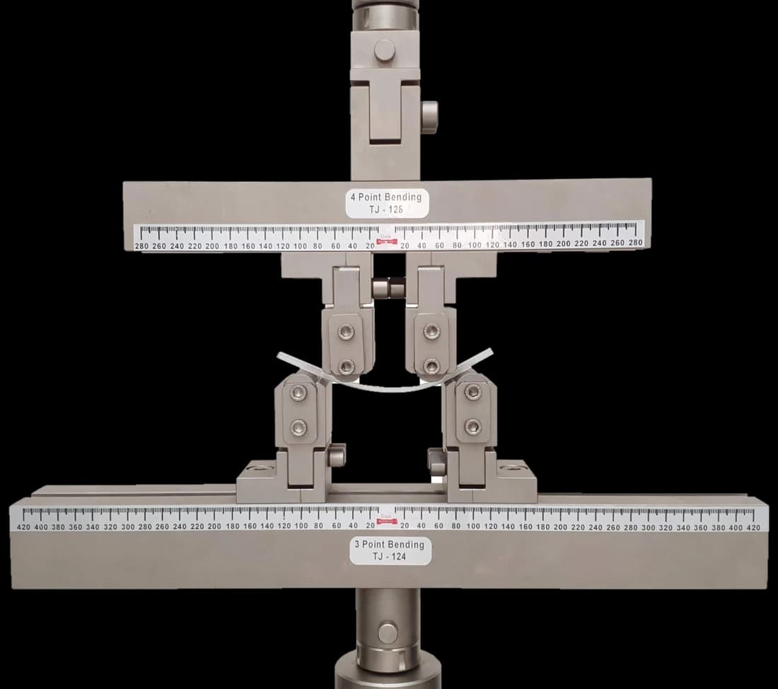
Third-point loading is a four-point bend arrangement: two supports and two loading blocks at the third points. Every block has to be able to rotate and to maintain even contact across the full beam width, so a beam whose faces are not perfectly plane still bears evenly.

Specifications
Self-identifying

Load Cells

A standard 150 mm square beam fails in the tens of kilonewtons, far below the capacity of the frame usually available. A cell sized for the beam is what makes the slow specified ramp controllable.

Specifications

What the report has to contain

  • Reference to ASTM C78/C78M and the edition
  • Whether the beam was moulded or sawn, and the preparation standard
  • Span and loading configuration
  • Age at test and curing history
  • Time out of water before testing
  • Loading rate
  • Maximum load for each beam
  • Beam width and depth measured at the fracture
  • Fracture location relative to the middle third
  • Modulus of rupture, mean and the number of specimens

What the machine must be capable of

Failure loads for a standard 150 mm square beam sit in the tens of kilonewtons, so a frame of 100 kN upwards covers ordinary work. Force accuracy to ASTM E4 is the requirement, and a controllable slow load rate matters as much as capacity.

The fixture carries the requirement. Support and loading blocks must be capable of rotating and of maintaining even contact across the full beam width, so that a beam whose faces are not perfectly plane still bears evenly. Spans are set accurately because span enters the calculation directly. No extensometer is required.

What goes wrong in practice

Beams allowed to dry before testing are the commonest and most invisible error. Loading faster than the specified rate raises the apparent strength. Bearing blocks that cannot rotate concentrate load on one corner of a slightly warped beam. And quoting a centre-point result against a third-point specification overstates the strength of the concrete, which is why C293 carried the warning it did.

Third-point against centre-point loading

The reason one of these two documents survives and the other does not.

Third point (C78)Centre point (C293)
StatusCurrentWithdrawn 2025, no replacement
Load pointsTwo, at the third pointsOne, at mid-span
Middle thirdConstant moment, zero shearMoment peaks at a single section
Failure can occurAnywhere in the middle thirdOnly at the load point
Result on the same concreteLowerHigher
An alternative to the otherNoNo — C293 said so itself

Quoting a centre-point modulus of rupture against a third-point specification overstates the concrete. C293 carried an explicit statement that it is not an alternative to C78, and its withdrawal has not made that any less true of historical data.

Questions we are asked about this test

What is ASTM C78?

ASTM C78, published as C78/C78M, determines the flexural strength of concrete using a simple beam under third-point loading. The beam is supported near its ends and loaded at two points, each a third of the span from a support, until it breaks, and the result is reported as the modulus of rupture. The current edition is C78/C78M-22, with revision work registered under WK93728.

What happened to ASTM C293?

C293/C293M-16, the centre-point loading method, was withdrawn in 2025 and the ASTM catalogue names no replacement. It was never an alternative to C78 — the standard said so itself — because centre-point loading returns a higher modulus of rupture on the same concrete. Historical C293 data remains what it was, and it should not be compared directly with C78 results.

Why does third-point loading give a lower result?

Because it lets the beam choose where to break. Third-point loading produces a constant bending moment and zero shear over the middle third of the span, so failure occurs wherever that region is weakest. Centre-point loading concentrates the maximum moment at a single section, and the beam can only fail there whether or not that is the weakest concrete in it. Testing a larger volume at peak stress finds more flaws, which is why the third-point figure is lower and why it is the one specifications use.

What is modulus of rupture used for?

Concrete paving, principally. Highway and airfield agencies specify paving concrete on flexural strength rather than compressive strength, because an unreinforced slab fails in bending under wheel loads. It is also used for some precast elements and for fibre-reinforced concrete work, though there the post-crack behaviour measured by ASTM C1609/C1609M usually matters more than the peak.

Why must the beams be kept wet until testing?

Because drying puts the outer fibres of the beam into tension before the machine does. Surface moisture leaves faster than moisture in the core, the surface tries to shrink, and the restraint from the interior loads exactly the fibres this test is about to load further. A beam left in a warm laboratory for an hour can read materially low, and nothing about its appearance gives that away.

Is modulus of rupture the tensile strength of the concrete?

No. It is computed from beam theory, which assumes the material stays elastic right up to failure — and concrete does not. The stress distribution across the beam at failure is not linear, so the calculated extreme fibre stress overstates the real tensile capacity. Modulus of rupture is a design convention that works because it is applied consistently, and it is higher than both splitting tensile strength and direct tensile strength on the same mix.

What machine does it need?

A frame of 100 kN upwards covers ordinary beam sizes, with force accuracy to ASTM E4. The controlling requirements are elsewhere: a slow, steady load rate at 0.9 to 1.2 MPa/min of extreme fibre stress, an accurately set span because span enters the calculation directly, and loading and support blocks that can rotate to bear evenly across the full width of a beam that is never perfectly plane.


Running ASTM C78/C293 on the Series 7200 and Series 9000

Dak verifies against whichever standard the method names, and where a class applies our frames sit a class tighter than it asks.

The method asks forDak supplies
CapacityTens of kN for a standard 150 mm square beamLoad cells from 1 kg to 60 ton on the Series 7200, and 0.5 to 100 kN on the Series 9000
Force accuracyASTM E4Verified to ASTM E4, and to ISO 7500-1 Class 0.5
GrippingThird-point bend rig with support and loading blocks free to rotate and bear evenly across the full beam widthOur bend fixtures, built to the specimen
EnvironmentBeams kept wet until the moment of testing; drying shrinkage loads the same outer fibres the test loads3009 series chambers, −150 °C to +400 °C — temperature only

This page describes the method as practised. The governing text is the current edition from the issuing body. Tell us what you are testing and we will answer with the machine, the fixture and a quotation.

Materials tested to it

The test it standardises

Other standards explained