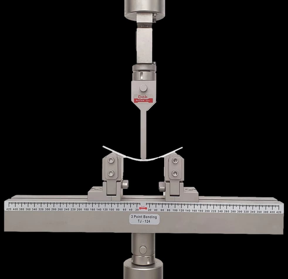
Three Point Bend Fixture
Support and loading rollers of the specified radius, free to rotate, with the span adjustable across the whole 400 to 1000 mm range. Span accuracy matters because span is cubed in the modulus expression.
SpecificationsTesting standard
Wood-based panels — Determination of modulus of elasticity in bending and of bending strength
Written and technically reviewed by Dak System Inc. engineeringLast reviewed
EN 310 bends a 50 mm wide strip of wood-based panel flatwise in three-point loading and reports two results from one test: the apparent modulus of elasticity in bending, and the bending strength. It applies to panels of nominal thickness 3 mm and above. The edition in force is EN 310:1993.
A rectangular strip of panel is supported near its ends and loaded through a single roller at mid-span, so it is bent flatwise. Load and mid-span deflection are recorded together, giving two results from one test: the apparent modulus of elasticity in bending from the slope of the elastic part of the curve, and the bending strength from the maximum load.
The word *apparent* in the title of the modulus is deliberate. A three-point bend measurement on a short span includes shear deflection as well as bending deflection, and the standard does not separate them, so the figure is a stiffness of the panel in this configuration rather than a pure elastic constant.
Wood-based panels — particleboard, MDF, OSB, plywood — are structural sheet materials, and stiffness and bending strength are how they are specified. A shelf that sags, a soft floor deck and a sheathing panel that cannot take wind load are all bending problems, and this is the number behind all three.
The method applies to panels of nominal thickness 3 mm and above. Both results are reported in the two panel directions where the panel is directional: OSB and plywood are strongly anisotropic, and a single figure describes only the direction it was measured in.
The formulae are published in the standard and are conventional beam theory. Modulus of elasticity is given by
E = l₁³(F₂ − F₁) / 4bt³(a₂ − a₁)
and bending strength by
f = 3F_max l₁ / 2bt²
where l₁ is the span, b the specimen width, t the thickness, F the load and a the corresponding deflection. Both are ordinary three-point bend expressions, which is why span, width and thickness have to be measured on each specimen rather than taken from the nominal values.

The span rule is the part that catches people out, because it has both a multiplier and two hard limits.
l₁³ (F₂ − F₁) / [4 b t³ (a₂ − a₁)]
Conventional three-point beam theory. Span, width and thickness are measured on each specimen rather than taken from nominal values.
3 F_max l₁ / (2 b t²)
A three-point measurement includes shear deflection as well as bending
The standard does not separate them, so the figure is a stiffness of the panel in this configuration rather than a pure elastic constant.

Support and loading rollers of the specified radius, free to rotate, with the span adjustable across the whole 400 to 1000 mm range. Span accuracy matters because span is cubed in the modulus expression.
SpecificationsA 50 mm strip fails at hundreds of newtons to a few kilonewtons. A cell sized for the panel is what resolves the straight part of the curve the modulus is taken from, which is at a fraction of the failure load.
SpecificationsFailure loads are modest — commonly hundreds of newtons to a few kilonewtons for a 50 mm strip — so a frame of 5 to 50 kN with a load cell sized for the panel and force accuracy to ISO 7500-1 Class 1 is appropriate.
The rate is set by outcome rather than by number: loading is adjusted so that maximum load is reached within 60 ± 30 s. That has to be established for each panel type, which means the first specimen of a batch is used to find the rate.
Deflection has to be measured at mid-span on the specimen. Crosshead travel includes the machine, the fixture and any bedding of the specimen onto the supports, and since deflection is in the denominator of the modulus expression, taking it from the crosshead gives a modulus that is too low.
Support and loading rollers of the specified radius are needed, free to rotate, with the span adjustable across the 400 to 1000 mm range.
Deflection from the crosshead is the error that most often reaches a report. Thickness taken as nominal rather than measured is the second, and it is magnified threefold in the modulus. A span set to a convenient round number rather than to 20 times the thickness changes both results. And unconditioned specimens give a spread that reads as variable board.
EN 310 and EN 319 answer different questions about the same board, and a board can pass one and fail the other.
| EN 310 | EN 319 | |
|---|---|---|
| Loads | The panel in flatwise bending | The panel in tension through its thickness |
| Dominated by | The dense surface layers | The weak core |
| Result | Modulus of elasticity and bending strength | Internal bond, in N/mm² |
| Specimen | A 50 mm wide strip on a 400 to 1000 mm span | A 50 mm square bonded between blocks |
| Force needed | Hundreds of newtons to a few kN | A few hundred newtons to about 1 kN |
| Finds | Sag and structural adequacy | Press and resin problems |
Bending is carried mostly by the dense faces, so a board with a weak, under-cured core can still bend acceptably. That is why EN 319 exists and why panel product standards specify both.
EN 310 is the European method for determining the modulus of elasticity in bending and the bending strength of wood-based panels. A 50 mm wide strip is bent flatwise in three-point loading while load and mid-span deflection are recorded, giving both results from a single test. It applies to panels of nominal thickness 3 mm and above. The edition in force is EN 310:1993, which has not been revised since publication.
It is 20 times the nominal thickness of the panel, but not less than 400 mm and not more than 1000 mm. That means the multiplier governs only in the middle of the thickness range: on a thin panel the 400 mm minimum takes over, and on a thick one the 1000 mm maximum does. Getting this wrong changes both results, because span appears in both formulae.
Because a three-point bend measurement over a relatively short span includes deflection from shear as well as from bending, and EN 310 does not separate the two. The number is therefore the stiffness of that panel in that test configuration rather than a pure elastic constant of the material. It is entirely usable — everyone in the industry compares against it — but it is not a true E and the standard is careful to say so.
Because it appears cubed in the modulus expression. A two percent error in thickness becomes a six percent error in the modulus, and nominal thicknesses on wood-based panels are nominal in earnest — a board sold as 18 mm may sit anywhere in a tolerance band. Using the nominal figure introduces a systematic error that no amount of careful testing recovers.
Because the crosshead moves further than the specimen deflects. Machine compliance, fixture flex and the specimen bedding onto the support rollers all add travel, and deflection sits in the denominator of the modulus expression — so the modulus comes out low. A deflectometer at mid-span measures the panel. This is the error that most often reaches a report on this method.
Because the right crosshead speed depends on the panel: a thin, flexible MDF and a thick, stiff plywood reach maximum load at very different rates of travel. Specifying that the maximum load is reached within 60 ± 30 s makes the loading rate comparable in terms that matter to the material. In practice the first specimen of a batch is used to find the speed that achieves it.
For any directional panel, yes. OSB and plywood are strongly anisotropic by construction, and their bending properties along and across the panel can differ by a large factor. A single figure describes only the direction it was measured in, and a report that does not say which direction it came from cannot be used. Particleboard and MDF are much closer to isotropic in-plane, but the direction is still recorded.
Dak verifies against whichever standard the method names, and where a class applies our frames sit a class tighter than it asks.
| The method asks for | Dak supplies | |
|---|---|---|
| Capacity | Low — hundreds of newtons to a few kN for a 50 mm wide strip | Load cells from 1 kg to 60 ton on the Series 7200, and 0.5 to 100 kN on the Series 9000 |
| Force accuracy | ISO 7500-1 Class 1 | ISO 7500-1 Class 0.5 — a class tighter than the method asks |
| Strain measurement | An extensometer of the class the method specifies | Certified to ISO 9513 Class 1 and ASTM E83 — non-contact video, clip-on and high-elongation |
| Gripping | Three-point bend rig with rollers of specified radius and an adjustable span from 400 mm to 1000 mm | Our bend fixtures, built to the specimen |
| Environment | Conditioned before test; wood-based panels are hygroscopic and both results move with moisture content | 3009 series chambers, −150 °C to +400 °C — temperature only |
This page describes the method as practised. The governing text is the current edition from the issuing body. Tell us what you are testing and we will answer with the machine, the fixture and a quotation.