Testing standard

ASTM D143

Standard Test Methods for Small Clear Specimens of Timber

Written and technically reviewed by Dak System Inc. engineeringLast reviewed

ASTM D143 is the American battery of mechanical tests for wood measured on small clear specimens — pieces free of knots, checks and other defects, so the result describes the species rather than the individual piece. It covers static bending, compression parallel and perpendicular to the grain, hardness, shear parallel, cleavage, tension parallel and perpendicular, impact bending, toughness and nail withdrawal, at a primary 2 by 2 in. (50 by 50 mm) cross section or, for two of those tests only, a secondary 1 by 1 in. (25 by 25 mm) section.

At a glance

Test type
Tensilethe specimen is pulled apart
Published by
ASTM
Edition
D143-25

What the test does

D143 is a battery rather than a single test. On small pieces of wood free of knots, checks and other defects it runs static bending, compression parallel and perpendicular to the grain, hardness, shear parallel, cleavage, tension parallel and perpendicular, impact bending, toughness and nail withdrawal.

The point of a small clear specimen is that it isolates the material from the piece. A structural timber fails where its worst knot is; a clear specimen measures what the wood itself can do, which is what species comparison and allowable-stress work need. D143 and D198, its structural-size counterpart, are described in D143 as together affording a basis for establishing allowable stresses.

What it measures, and why it matters

Two specimen sizes run through the standard and they are not interchangeable. The primary method uses a 2 by 2 in. (50 by 50 mm) cross section, and the standard advises using it wherever possible because that section embraces a number of growth rings and is less influenced by the difference between earlywood and latewood.

The secondary method uses 1 by 1 in. (25 by 25 mm) and exists only for static bending and compression parallel, for when clear material of the larger section cannot be found. Six tests stay at 2 by 2 in. regardless, and toughness and tension parallel use their own smaller sections. The standard cautions that results between two different specimen sizes are not necessarily directly comparable, and pooling them is the classic error with this method.

Specimen sizes and conditioning

Two sizes run through the standard and they are not interchangeable. The standard says so itself, and pooling them is the classic error with this method.

Primary method
2 by 2 in. (50 by 50 mm) cross sectionAdvisable wherever possible: it embraces a number of growth rings and is less influenced by earlywood and latewood differences than a smaller section.
Secondary method
1 by 1 in. (25 by 25 mm) cross sectionEstablished for static bending and compression parallel to grain ONLY, for when clear material of the larger section and length cannot be obtained.
Fixed at 2 by 2 in.
Impact bending, compression perpendicular, hardness, shear parallel, cleavage, tension perpendicular
Own smaller sections
Toughness and tension parallel to grain
Static bending specimen
2 × 2 × 30 in. (50 × 50 × 760 mm) or 1 × 1 × 16 in. (25 × 25 × 410 mm)
Static bending span
28 in. (710 mm) primary · 14 in. (360 mm) secondaryChosen to maintain a minimum span-to-depth ratio of 14.
Bearing block
3 in. (76 mm) radius, chord ≥ 3 13/16 in. (97 mm) · 1 1/2 in. (38 mm) radius, chord ≥ 2 in. (50 mm)Fixed against rotation, and made of a material that will not appreciably deform under load.
Growth ring orientation
Load applied to the tangential surface nearest the pith
Compression parallel specimen
2 × 2 × 8 in. (50 × 50 × 200 mm) or 1 × 1 × 4 in. (25 × 25 × 100 mm)End grain surfaces parallel to each other and at right angles to the longitudinal axis.
Temperature at test
68 ± 6 °F (20 ± 3 °C)Recorded as a specific part of the test record.
Humidity
No numeric requirementThe standard says only that humidity control is desirable. There is no 23 °C / 50 % RH atmosphere in D143 — do not import one from a plastics standard.
Moisture content
Dry air-dry specimens to approximately constant weightWeigh each specimen immediately before test; afterwards cut a moisture section about 1 in. (25 mm) long from near the point of failure.
Ends slightly drier than the body
For compression parallelClause 9.5: it is how you get the failure to develop in the body of the specimen rather than at the ends.


Speed of testing

There is no single D143 rate. Each method sets its own, and compression parallel sets a strain rate rather than a crosshead speed.

Static bending, primary
0.10 in. (2.5 mm) per minute
Static bending, secondary
0.05 in. (1.3 mm) per minute
Compression parallel
0.003 in./in. (mm/mm) of nominal specimen length per minuteA strain rate, so the crosshead moves at 0.024 in./min on the 8 in. primary specimen and 0.012 in./min on the 4 in. secondary — arithmetic on the standard's rule, not a figure it prints.
Past maximum load, bending
Customarily to 6 in. (152 mm) deflection, or until the specimen will not carry 200 lbf (890 N)Practice3 in. (76 mm) and 50 lbf (222 N) for secondary specimens. The standard calls this customary, not required.
Other methods
Set in their own clauses, which are not published openlyNo rate is given here for impact bending, toughness, compression perpendicular, hardness, shear, cleavage, tension or nail withdrawal.

Calculations

Modulus of ruptureMOR

MOR = 3PL / (2bd²)

P
maximum load, lbf or N
L
span, in. or mm
b
specimen width, in. or mm
d
specimen depth, in. or mm

The standard centre-loading flexure relationship, applied to the 28 in. or 14 in. span. D143 fixes the span so that this stays valid at a span-to-depth ratio of at least 14.

Modulus of elasticityMOE

MOE = PL³ / (48 Δ I)

Δ
deflection of the neutral plane at mid-length, in. or mm
I
second moment of area, bd³/12

Δ must be the neutral-plane deflection taken with the yoke, referenced to points above the supports. Crosshead travel includes machine compliance and inflates the result.

Compressive stress parallel to grainσc

σc = P / A

A
cross-sectional area, 4 in² or 1 in² nominal

How a static bending test runs

  1. 01Select clear material — no knots, checks or other defects — and cut to 2 × 2 × 30 in., or 1 × 1 × 16 in. if the larger clear section cannot be found.
  2. 02Dry air-dry specimens to approximately constant weight and recondition anything whose moisture changed during preparation.
  3. 03Bring the specimen to 68 ± 6 °F (20 ± 3 °C) and record the temperature.
  4. 04Weigh the specimen immediately before test.
  5. 05Set the span to 28 in. (710 mm), or 14 in. (360 mm) for a secondary specimen.
  6. 06Adjust the knife edges laterally to take up any twist in the stick.
  7. 07Place the specimen so load reaches the tangential surface nearest the pith.
  8. 08Fit the yoke so deflection is read on the neutral plane relative to points above the supports.
  9. 09Load continuously at 0.10 in. (2.5 mm) per minute, or 0.05 in. (1.3 mm) for a secondary specimen.
  10. 10Record load and deflection at intervals no coarser than 0.10 in. (2.5 mm), and after any abrupt change in load; continuous acquisition is preferred.
  11. 11Classify the failure as brash or fibrous.
  12. 12Cut a moisture section about 1 in. (25 mm) long from near the point of failure.

Deflection must come from the yoke, not the crosshead. Machine compliance inside a crosshead reading is indistinguishable from specimen deflection and drives modulus of elasticity up.

Grips and fixtures for this method

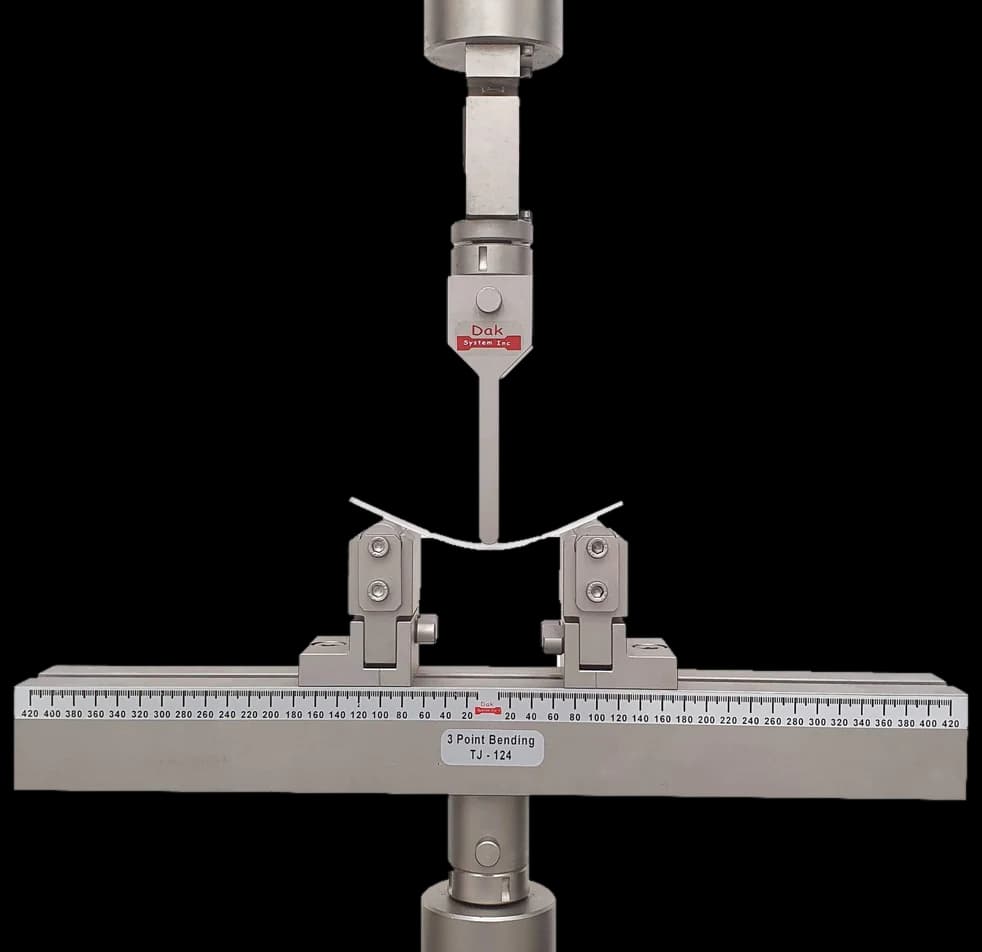
Three point bending fixture with an adjustable span and a graduated beam
Adjustable spanTJ-124

Three Point Bend Fixture

Static bending is centre loading on a fixed span with laterally adjustable knife edges, so a stick with slight twist still beds down on both supports. The bearing plates and rollers sit close enough to the central plane that the distance from support point to that plane does not exceed the specimen depth.

Specifications
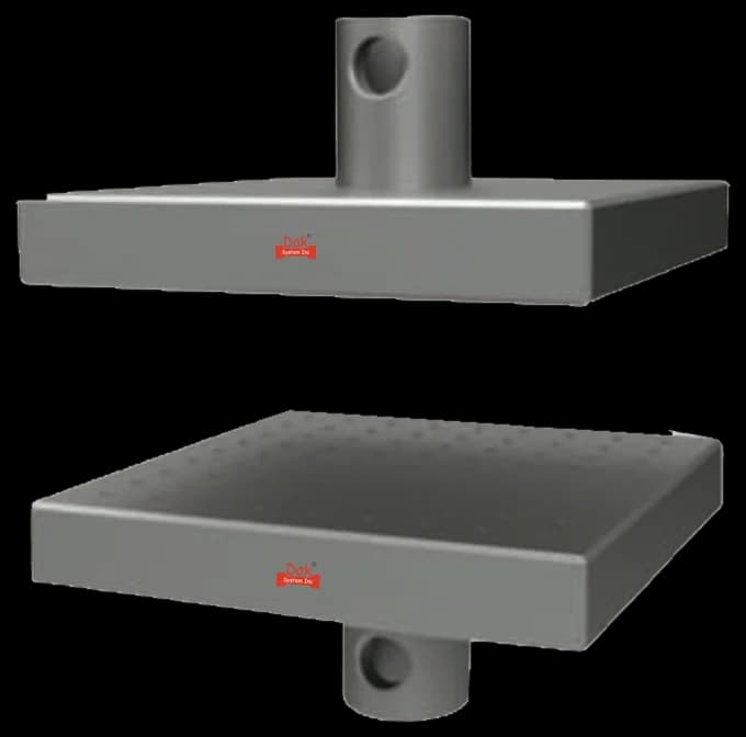
Direct compression fixture platens
5 to 400 kNTJ-125

Direct Compression Fixture

Compression parallel to the grain needs at least one platen on a spherical bearing, so load distributes over end grain that is never perfectly square. Without it the specimen crushes a corner first and fails at the end rather than in the body.

Specifications
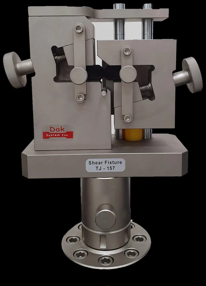
Shear fixture mounted on a load frame adapter
TJ-157

Shear Test Fixture

Shear parallel to the grain runs in its own notched-block rig rather than on platens. Its geometry sits in a clause that is not published openly and is not reproduced here.

Specifications

What the report has to contain

  • Reference to ASTM D143 and the edition
  • Species and, where known, the source and sampling basis
  • Whether the primary or secondary method was used
  • Specimen dimensions and span
  • Moisture content, from the section cut near the failure
  • Weight immediately before test
  • Temperature at the time of test
  • Rate of loading used
  • Maximum load, and the property calculated from it
  • Deflection or deformation, and the class of device used to measure it
  • Failure classification as brash or fibrous
  • Number of specimens and the scatter

What the machine must be capable of

Speed is set per test and it is not one number. Static bending runs at 0.10 in. (2.5 mm) per minute for the primary specimen and 0.05 in. (1.3 mm) per minute for the secondary. Compression parallel is given as a strain rate instead — 0.003 in. per in. of nominal length per minute — so the absolute crosshead speed differs between the two specimen lengths.

Displacement measurement carries stated classes, verified to Practice E2309: Class A for compression parallel, Class B within the proportional limit in bending, Class C acceptable beyond it. Force verification points at Practice E4, and the required accuracy percentage sits in the calibration clauses, which are not published openly.

The fixtures are specific. Bending needs laterally adjustable knife-edge supports with bearing plates and rollers, so a slightly twisted specimen still seats. Compression parallel needs at least one platen on a spherical bearing. Bending deflection is taken on the neutral plane with a yoke, referenced to points above the supports.

What goes wrong in practice

Deflection read at the crosshead rather than on the neutral axis is the most damaging habit: machine compliance enters the reading and modulus of elasticity comes out high. The yoke exists to remove it.

Compression parallel specimens that crush at the ends rather than in the body are the second recurring problem. The standard's own remedy is a spherical bearing platen and ends held at a very slightly lower moisture content than the body.

Moisture drift across a test day undoes everything else, which is why the conditioning clause is written as firmly as it is. Inch-pound units are normative here and SI is informative, so reporting SI as though it governed is a documentation error.

Primary and secondary specimens

The choice is not a convenience. It changes which tests are available and it makes the results a separate population.

Primary methodSecondary method
Cross section2 × 2 in. (50 × 50 mm)1 × 1 in. (25 × 25 mm)
Available forEvery test in the standardStatic bending and compression parallel only
Static bending specimen2 × 2 × 30 in. (50 × 50 × 760 mm)1 × 1 × 16 in. (25 × 25 × 410 mm)
Bending span28 in. (710 mm)14 in. (360 mm)
Bending rate0.10 in. (2.5 mm)/min0.05 in. (1.3 mm)/min
Bearing block radius3 in. (76 mm)1 1/2 in. (38 mm)
Compression specimen2 × 2 × 8 in. (50 × 50 × 200 mm)1 × 1 × 4 in. (25 × 25 × 100 mm)
Compression gauge length≤6 in. (150 mm)2 in. (50 mm)

The standard cautions in its own Introduction that test results between two different sizes of specimen are not necessarily directly comparable, and advises the primary method wherever possible. A dataset mixing the two is not one dataset.

ASTM D143 or ASTM D198

ASTM D143ASTM D198
SpecimenSmall, clear, defect-freeLumber in structural sizes, defects included
What it measuresThe materialThe piece, as it would be used
Typical useSpecies comparison, clear wood strength valuesGrading, allowable stress verification, connections
Bending spanFixed at 28 in. or 14 in.Set by the member

D143 itself says the two together afford a basis for establishing allowable stresses. A clear-wood figure is an upper bound on what a knotty structural member will do, never a substitute for testing one.

Questions we are asked about this test

What is ASTM D143?

It is the American set of test methods for determining the mechanical properties of wood using small clear specimens — pieces selected free of knots, checks and other defects. It covers static bending, compression parallel and perpendicular to the grain, hardness, shear parallel, cleavage, tension parallel and perpendicular, impact bending, toughness and nail withdrawal. The methods were originally approved in 1922 and the current edition is D143-25.

Why test a clear specimen when real timber has knots?

Because the two questions are different. A structural member fails wherever its worst defect is, so testing one tells you about that piece. A clear specimen measures what the species itself can do, which is what you need to compare species, to establish clear wood strength values and to derive allowable stresses. D143 says explicitly that it and D198, the structural-size method, together afford a basis for establishing those stresses.

What is the difference between the primary and secondary methods?

The cross section. Primary is 2 by 2 in. (50 by 50 mm) and secondary is 1 by 1 in. (25 by 25 mm). Primary is advised wherever possible, because that section takes in several growth rings and is less swayed by the difference between earlywood and latewood. Secondary exists only for static bending and compression parallel to the grain, for material from which a clear 2 by 2 in. piece of the required length cannot be cut.

Can I compare a 1 by 1 in. result with a 2 by 2 in. result?

No. The standard cautions in its own Introduction that results between two different specimen sizes are not necessarily directly comparable. They are separate populations and mixing them into one dataset is the commonest error made with this method. Say which method produced each figure, every time.

What speed does ASTM D143 use?

There is no single rate — each method sets its own. Static bending runs at 0.10 in. (2.5 mm) per minute on the primary specimen and 0.05 in. (1.3 mm) per minute on the secondary. Compression parallel to the grain is specified as a strain rate instead, 0.003 in. per in. of nominal specimen length per minute, which works out to different crosshead speeds for the 8 in. and 4 in. specimens.

Why is my modulus of elasticity too high?

Almost always because deflection was taken from crosshead travel. That reading contains the machine's own compliance and the seating of the specimen on the supports, neither of which is the wood bending. D143 requires the deflection of the neutral plane at mid-length, measured with a yoke referenced to points in the neutral plane above the supports, using a device capable of at least a Class B rating to Practice E2309 within the proportional limit.

Why do my compression specimens crush at the ends?

Either the end grain is not square and parallel, or there is no spherical bearing on the platen, or the ends are wetter than the body. The standard addresses all three: it asks for special care in preparing the end surfaces, requires at least one platen on a spherical bearing, and notes that failures develop in the body most reliably when the ends are at a very slightly lower moisture content than the body.

What conditioning atmosphere does D143 require?

A temperature only. Specimens must be at 68 ± 6 °F (20 ± 3 °C) when tested, and the temperature is recorded as a specific part of the test record. Air-dry specimens are dried to approximately constant weight, and anything whose moisture changed during preparation is reconditioned. There is no numeric humidity requirement — the standard says only that humidity control is desirable, so do not import a 23 °C and 50 percent atmosphere from a plastics method.

ASTM D198 is the structural-size counterpart and the two are designed to be read together. D5536 covers sampling forest trees to obtain clear specimens, D2555 establishing clear wood strength values, D2395 density, D4442 moisture content, D4761 lumber and wood-based structural materials, D3043 structural panels in flexure. Practice E4 verifies force and Practice E2309 the displacement devices.

Running ASTM D143 on the Series 7200 and Series 9000

Dak verifies against whichever standard the method names, and where a class applies our frames sit a class tighter than it asks.

The method asks forDak supplies
CapacityNot stated by the standard; it follows from species and specimen. A dense hardwood in compression parallel on the 2 by 2 in. section reaches the tens of kilonewtons, and static bending on a 28 in. span far less.Load cells from 1 kg to 60 ton on the Series 7200, and 0.5 to 100 kN on the Series 9000
Force accuracyunknown — D143 points at ASTM E4 for force verification and the required percentage sits in its calibration clauses, which were not retrievedISO 7500-1 Class 0.5 — the method sets no class of its own
Strain measurementAn extensometer to ASTM E2309 Class A for compression parallel; Class B within the proportional limit in static bending; Class C beyond it, gauge length compression parallel: not exceeding 150 mm (6 in.) for the primary specimen, 50 mm (2 in.) for the secondaryCertified to ISO 9513 Class 1 and ASTM E83 non-contact video, clip-on and high-elongation
GrippingLaterally adjustable knife-edge supports with bearing plates and rollers and a fixed radiused bearing block for static bending; a platen on a spherical bearing for compression parallel; a yoke for neutral-plane deflection; separate rigs for shear parallel, cleavage and nail withdrawal.Our shear fixtures or compression anvils, built to the specimen
EnvironmentSpecimens at 68 plus or minus 6 degrees Fahrenheit (20 plus or minus 3 degrees Celsius) at the time of test, with the temperature recorded. Air-dry specimens dried to approximately constant weight. No numeric humidity is specified — the standard says only that humidity control is desirable.3009 series chambers, −150 °C to +400 °C — temperature only

This page describes the method as practised. The governing text is the current edition from the issuing body. Tell us what you are testing and we will answer with the machine, the fixture and a quotation.

Materials tested to it

The test it standardises

Industries that test to it

Other standards explained