
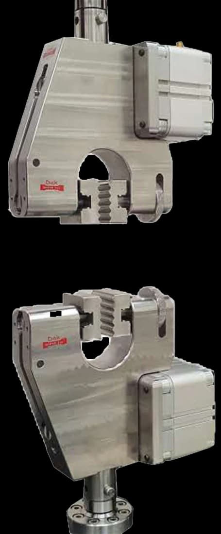
Standard 25 mm
Pneumatic Vice Action Grip
Flat vice-action faces hold each thin arm across its full width at a constant, gentle pressure — the arms are the specimen here, so a grip that marks or cuts them changes the result.
Specifications
Testing standard
Standard Test Method for Peel Resistance of Adhesives (T-Peel Test)
Written and technically reviewed by Dak System Inc. engineeringLast reviewed
ASTM D1876 is the T-peel test for adhesive bonds between two flexible adherends. The unbonded ends are bent away from each other to form a T and pulled apart, splitting the bond progressively. It reports peel resistance — the average force per unit width while the peel front advances steadily, excluding the initial load spike.
From the test method to your testing system
Explore the DAK machines already listed for ASTM D1876, then review the grips, measurement and setup requirements below.
 Universal Testing MachineSeries 7200Explore the machine →
 Universal Testing MachineSeries 9000Explore the machine →
01Understand the method
Two flexible strips bonded together over most of their length are pulled apart. The short unbonded ends are bent away from each other and clamped in opposing grips, so the assembly forms a T. The crosshead separates the grips at a constant rate and the bond splits progressively along the joint, while force and head travel are recorded continuously through the separation.
The reported quantity is peel resistance: the average force per unit specimen width sustained while the peel front advances steadily, taken over a fixed length of peel and excluding the initial load spike. It is a lot-release number for tapes, films and laminates, and a screening number during adhesive formulation. It also grades surface preparation, since the same adhesive on a degreased and on an untreated adherend separates by a wide margin. It ranks bonds; it is not a design allowable for a joint of different geometry.
02Prepare the specimen and test settings
03Build the test setup on a DAK machine
Forces are modest. A film laminate peels at tens of newtons on a 25 mm strip and a toughened structural adhesive on thin metal arms at a few hundred, so a 100 N to 1 kN load cell covers almost all of this work, with 5 kN reserved for outliers. Capacity matching is the binding constraint rather than frame size: a 20 N peel plateau read on a 5 kN cell sits in the noise, and the fine structure of the trace is lost. The force-accuracy class required is set in the standard's own text.
The method fixes head speed at 254 mm/min (10 in./min), which separates the bond at 127 mm/min because both arms move. Peel is rate-sensitive, so the speed must be held constant, not merely averaged. Stroke matters more than it does in tension: recording the required 127 mm of peel after the initial peak needs roughly 250 to 300 mm of usable travel, and a short-stroke bench runs out mid-test.
No extensometer is used — the record is force against head travel. No dedicated peel fixture is called for either; the two bent arms go into plain opposing tension grips, mechanical vice-action or pneumatic side-action, with non-slip faces. Alignment is the critical detail: the arms must sit symmetric about the load axis. Testing is done in the same 23 °C, 50 % RH atmosphere used for conditioning.
Flat vice-action faces hold each thin arm across its full width at a constant, gentle pressure — the arms are the specimen here, so a grip that marks or cuts them changes the result.
SpecificationsDak verifies against whichever standard the method names, and where a class applies our frames sit a class tighter than it asks.
| The method asks for | Dak supplies | |
|---|---|---|
| Capacity | Modest forces on a 25 mm specimen — tens of newtons for a film laminate, a few hundred for a toughened structural adhesive on thin metal arms, so a 100 N to 1 kN load cell suits almost all work and vendors stock 100 N to 5 kN for the outliers. | Load cells from 1 kg to 60 ton on the Series 7200, and 0.5 to 100 kN on the Series 9000 |
| Force accuracy | unknown | ISO 7500-1 Class 0.5 — the method sets no class of its own |
| Gripping | Plain opposing tensile grips holding the two bent, unbonded arms of a T specimen — no peel fixture required | Our vice-action grips, built to the specimen |
| Environment | Standard laboratory atmosphere, about 23 °C and 50 % RH, with specimens conditioned at least 24 h before test | 3009 series chambers, −150 °C to +400 °C — temperature only |
04Run the test
The two arms must stay flexible throughout. Once an arm yields and holds a bend, part of the measured force is going into deforming metal rather than separating adhesive — and the trace still looks like a peel curve.
05Calculate, report and interpret
T = F_avg / w
Force per unit width. The averaging length is fixed in advance precisely so the figure cannot be improved by choosing a flattering window after the fact.
Arm yield is the commonest invalidation — a metal adherend that bends permanently absorbs work that is then reported as adhesion. Asymmetric clamping runs the peel front crooked across the width, and the trace drifts downward as the effective bonded width shrinks. Stick-slip peel gives a sawtooth trace as the crack alternately arrests and runs; the mean is meaningful, single points are not. Including the initial peak in the average inflates the result, sometimes by a factor of two.
06Compare methods and find answers
| ASTM D1876 | ASTM D903 | |
|---|---|---|
| Adherends | Both flexible | One rigid, one flexible |
| Geometry | T-peel | 180° peel |
| What is averaged | Fixed peel length, spike excluded | Running portion |
| Common rate | 254 mm/min | 305 mm/min |
| Chief failure to guard against | An arm taking a permanent set | The flexible member cracking when folded |
Both rank bonds and detect process drift; neither is a design allowable. Peel results depend on geometry, peel angle and adherend stiffness, so they do not transfer to a joint of different shape.
It is the ASTM T-peel test for adhesive bonds. Two flexible adherends are bonded over most of their length, the free ends are bent away from each other to form a T, and the grips pull them apart while the bond splits progressively. The result is peel resistance — average force per unit width over a fixed peel length.
When both adherends are flexible. D903 needs one rigid member for the flexible one to be peeled from; if you have two thin sheets, films or laminates, that geometry cannot be built and the T-peel is the right test. The reverse also holds — a rigid substrate cannot form a T-peel arm.
Because it reflects initiating the peel at one point rather than the bond's steady resistance to being peeled. Including it would make the result depend on how cleanly the unbonded ends were separated, which is a preparation artefact rather than a property of the adhesive.
So the number cannot be improved after the fact. A peel trace is uneven, and choosing which stretch of it to average once you have seen the data is a way of selecting a result rather than measuring one. Fixing the length beforehand removes that freedom.
The test stops being a peel test. Part of the measured force goes into permanently bending the arm rather than separating the adhesive, so the figure is inflated by an amount that depends on the adherend rather than the bond — and the trace still looks entirely plausible. Both arms have to bend without taking a set.
No. Like all peel tests it depends heavily on geometry, peel angle and adherend stiffness, so a figure from a 25 mm T-peel does not transfer to a joint of different shape. It is a lot-release and formulation-screening number, and it grades surface preparation very well — the same adhesive on a degreased and an untreated adherend separates by a wide margin.
Discuss your specimen, test requirements and reporting needs with DAK engineering.
This page describes the method as practised. The governing text is the current edition from the issuing body. Tell us what you are testing and we will answer with the machine, the fixture and a quotation.