
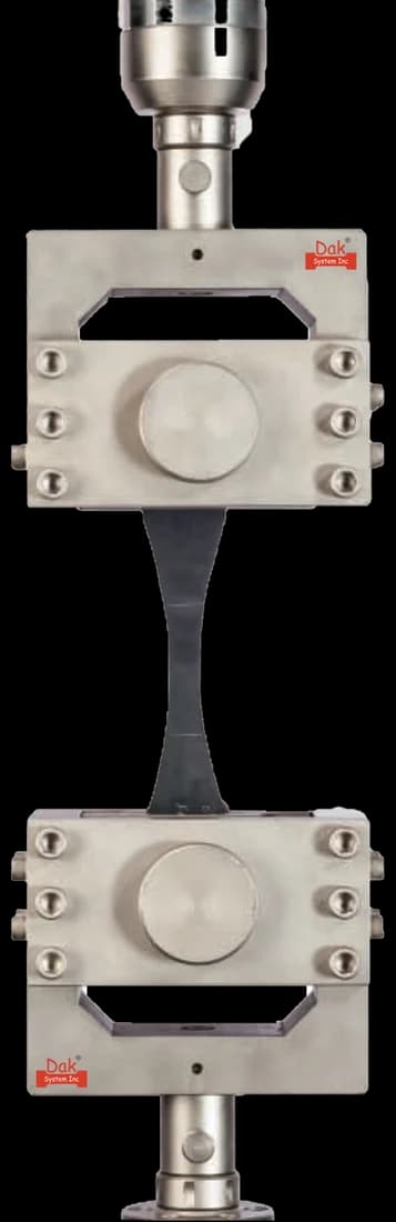
TJ-144
Heavy Duty Hydraulic Grips
Heavy duty hydraulic wedge grips hold a constant clamping force as the specimen necks, which is what prevents late slippage on a high-strength bar.
Specifications
Testing standard
Metallic materials — Tensile testing — Part 1: Method of test at room temperature
Written and technically reviewed by Dak System Inc. engineeringLast reviewed
IS 1608 is the Indian Standard for tensile testing of metallic materials at ambient temperature. It is harmonised with ISO 6892-1 and specifies the specimen forms, strain rates, and calculations for yield and proof strength, tensile strength, elongation and reduction of area. It is the reference method behind most Indian steel and metal product acceptance.
From the test method to your testing system
Explore the DAK machines already listed for IS 1608, then review the grips, measurement and setup requirements below.
 Universal Testing MachineSeries 7200Explore the machine →
 Universal Testing MachineSeries 9000Explore the machine →
01Understand the method
A specimen of defined form — a machined round or flat coupon, or a full-section product such as reinforcing bar or wire — is gripped in wedge grips and pulled along its axis at a controlled rate until it fractures. An extensometer is fitted across the gauge length where yield or proof strength is required. Force is recorded against extension throughout. After fracture the two halves are fitted back together and the final gauge length and minimum cross-section are measured, giving elongation after fracture and reduction of area. Rate control follows ISO 6892-1: one strain rate held through yield or proof strength, a faster one to fracture, with the figures given below.
The method yields the properties that virtually every metal product is specified on: yield or proof strength, tensile strength, elongation after fracture and reduction of area. Yield strength is what a structure is designed against; tensile strength is the ultimate capacity; elongation and reduction of area describe ductility, which determines whether a material deforms visibly before it fails or breaks without warning. In Indian practice IS 1608 is the method called up by the product standards behind construction steel, reinforcing bar, structural sections, fasteners and wire, so it sits underneath a very large share of routine material acceptance.
02Prepare the specimen and test settings
The specimen forms follow ISO practice, and the choice between proportional and non-proportional gauge lengths is the one that most affects a reported elongation.
Elongation values are meaningless without the gauge length they were measured over. A 20 % elongation on 5.65√S₀ and a 20 % on a fixed 50 mm gauge describe different material behaviour, and product standards are specific about which applies.
IS 1608 (Part 1):2022 is identical under dual numbering with ISO 6892-1:2019, so the rate ranges below are its own. Method A is strain-rate control and is the recommended one; Method B sets a stress rate in the elastic range instead.
03Build the test setup on a DAK machine
Force measurement to Class 1 across a range that may run from a few kilonewtons for wire to several hundred for structural sections, together with the frame capacity and grip range to match. Wedge grips need inserts matched to the product form — flat for plate, V-grooved for round bar, and serrated for ribbed rebar, which a smooth face cannot hold. Hydraulic grips maintain clamping force as the specimen necks, which prevents late slippage on high-strength material. A Class 1 extensometer is needed for proof strength.
Rate control must hold the method's strain rates rather than approximate them. IS 1608 (Part 1):2022 is identical under dual numbering with ISO 6892-1:2019, so those are its rates. Method A, strain-rate control and the recommended one, runs at 0.00025 s⁻¹ ±20 % (0.015 min⁻¹) through the upper yield or proof strength, with a slower 0.00007 s⁻¹ range available where a specification calls for it, and then at 0.0067 s⁻¹ ±20 % (0.4 min⁻¹) to fracture. On an ordinary 10 mm round test piece — 50 mm proportional gauge length, 60 mm parallel length — a machine without closed-loop strain control runs those as crosshead speeds of about 0.9 mm/min and 24 mm/min. Method B, stress-rate control, allows 6 to 60 MPa/s in the elastic range for steel and anything else above 150 GPa, which on that 78.5 mm² section is a force rate of 0.47 to 4.7 kN/s.
Heavy duty hydraulic wedge grips hold a constant clamping force as the specimen necks, which is what prevents late slippage on a high-strength bar.
Specifications
Universal parallel wedge grips with inserts matched to the product — flat for plate and strip, V-grooved for round bar.
Specifications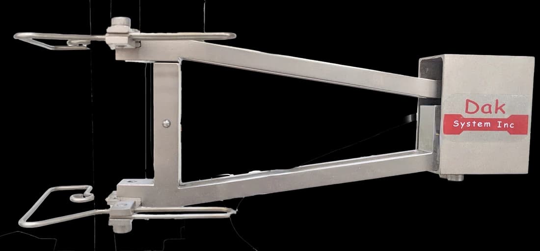
A clip-on extensometer is required for proof strength: Rp0.2 is defined against a 0.2 % non-proportional extension and cannot be derived from crosshead travel.
SpecificationsDak verifies against whichever standard the method names, and where a class applies our frames sit a class tighter than it asks.
| The method asks for | Dak supplies | |
|---|---|---|
| Capacity | Wide — from a few kilonewtons on small round specimens to over 600 kN on full-section structural products | Load cells from 1 kg to 60 ton on the Series 7200, and 0.5 to 100 kN on the Series 9000 |
| Force accuracy | IS 1828-1 / ISO 7500-1 Class 1 | ISO 7500-1 Class 0.5 — a class tighter than the method asks |
| Strain measurement | An extensometer to IS 12872 / ISO 9513 Class 1 for proof strength; Class 2 acceptable for elongation, gauge length 5.65√S₀ for proportional specimens, commonly 50 or 200 for non-proportional | Certified to ISO 9513 Class 1 and ASTM E83 — non-contact video, clip-on and high-elongation |
| Gripping | Wedge grips — hydraulic or mechanical — sized for the product, with round and flat jaw inserts | Our self-tightening serrated wedge grips, with V-jaws for round specimens, built to the specimen |
| Environment | Ambient, 10 °C to 35 °C unless otherwise specified | 3009 series chambers, −150 °C to +400 °C — temperature only |
04Run the test
05Calculate, report and interpret
Rm = Fm / S₀
ReH = FeH / S₀
Applies to materials showing a discontinuous yield, which includes most hot-rolled carbon steels.
Rp0.2 = Fp0.2 / S₀
Used where no clear yield point exists — cold-worked, stainless and most non-ferrous materials. It requires an extensometer; it cannot be derived from crosshead travel.
A = (Lu − L₀) / L₀ × 100
Z = (S₀ − Su) / S₀ × 100
Quoting an elongation without its gauge length is the most common reporting error and makes the figure unusable, since proportional and fixed-gauge results differ systematically. Deriving proof strength from crosshead travel rather than an extensometer is the most common measurement error, and it overstates the strain by including machine compliance. Running faster after yield to save time inflates tensile strength consistently enough that it never looks like scatter. On the bench, slippage in the grips on high-strength bar and fractures falling outside the gauge marks are the two recurring causes of a rejected test.
06Compare methods and find answers
| IS 1608 | ISO 6892-1 | ASTM E8/E8M | |
|---|---|---|---|
| Gauge length | 5.65√S₀ preferred | 5.65√S₀ preferred | Fixed gauge lengths preferred |
| Rate control | Strain-rate based, ISO-harmonised | Methods A and B | Rate ranges by material and stage |
| Yield convention | ReH / ReL, or Rp0.2 | ReH / ReL, or Rp0.2 | Yield point or 0.2 % offset |
| Used by | Indian product standards and BIS certification | International and European specifications | North American specifications |
IS 1608 is harmonised with ISO 6892-1, so results generally transfer between them. ASTM E8/E8M uses different preferred gauge lengths, which changes the reported elongation — that figure in particular should not be assumed to transfer between the ISO and ASTM families.
It is the Indian Standard for tensile testing of metallic materials at ambient temperature, harmonised with ISO 6892-1. It specifies specimen forms, gauge lengths, rate control and the calculations for yield and proof strength, tensile strength, elongation after fracture and reduction of area. Most Indian steel and metal product standards call up IS 1608 as their tensile method.
It is harmonised with it, which means the specimen forms, rate control approach and reported quantities follow ISO practice. In everyday use results transfer between the two, and a laboratory equipped to run one is equipped to run the other. The Indian standard exists so that BIS product standards can call up a national document, and it is the version cited in Indian certification and acceptance work.
Because elongation after fracture concentrates in the necked region, so a shorter gauge length contains a larger proportion of that concentrated deformation and reports a higher percentage. The proportional gauge length of 5.65√S₀ ties gauge length to cross-section so that specimens of different sizes are comparable. An elongation figure quoted without its gauge length cannot be used, and product standards are specific about which applies.
Yield strength where the material shows a discontinuous yield — a clear drop in load at the onset of plastic deformation, which most hot-rolled carbon steels do. Proof strength where it does not, which covers cold-worked steels, stainless grades and most non-ferrous metals. Proof strength at 0.2 % non-proportional extension requires an extensometer, since it is defined against a strain the crosshead cannot measure.
Yes, and it should be. Rebar is tested full-section because the rib pattern is part of the product and machining it away would test a different article. The nominal cross-sectional area from the product standard is used in the calculation rather than a measured one. The ribs also mean serrated grip faces are needed — a smooth face has nothing to hold on to.
You can, but only within the range the method allows. After the yield or proof strength has been determined the rate may go to 0.0067 s⁻¹ (0.4 min⁻¹) — about 24 mm/min of crosshead on a 60 mm parallel length — and no further. Beyond that, tensile strength rises with strain rate in most steels, so the test reports a higher strength than the material would give at the specified rate, and because the effect is consistent it never shows up as scatter that anyone would investigate.
Check what the product standard says, because practice varies. Many require the test to be repeated if the fracture falls outside the gauge marks or too close to a grip, since the elongation measurement assumes the neck formed within the marked length. Some allow a correction procedure. Either way the fracture location is recorded, because it is the evidence that the elongation figure is valid.
Discuss your specimen, test requirements and reporting needs with DAK engineering.
This page describes the method as practised. The governing text is the current edition from the issuing body. Tell us what you are testing and we will answer with the machine, the fixture and a quotation.