

Self-tighteningTJ-15
Universal Parallel Wedge Grips
Self-tightening parallel wedges hold a flat sheet test piece square to the load axis, which is what keeps the width reduction symmetrical along the gauge length.
Specifications
Testing standard
ISO 10113, Metallic materials — Sheet and strip — Determination of plastic strain ratio; ISO 10275, Metallic materials — Sheet and strip — Determination of tensile strain hardening exponent
Written and technically reviewed by Dak System Inc. engineeringLast reviewed
ISO 10113 determines the plastic strain ratio r of metallic sheet and strip, and ISO 10275 the tensile strain hardening exponent n. They are the ISO formability pair: r says how well the metal resists thinning as it is drawn, n says how quickly it hardens as it is stretched. Both come from a tension test to ISO 6892-1 and both are valid only up to maximum force.
From the test method to your testing system
Explore the DAK machines already listed for ISO 10113 / 10275, then review the grips, measurement and setup requirements below.
 Universal Testing MachineSeries 7200Explore the machine →
 Universal Testing MachineSeries 9000Explore the machine →
01Understand the method
Two measurements from the same kind of tensile test on the same kind of sheet coupon, often on the same test piece. ISO 10113 strains a test piece to a specified plastic strain and works out the plastic strain ratio r from the change in width and thickness — in practice from length and width, since length is easier to measure precisely and constancy of volume supplies the third strain. ISO 10275 fits the plastic part of the same curve to a power law and reports the exponent n as the slope of true stress against true plastic strain on logarithmic axes. Both are valid only up to maximum force: local necking begins there and the mathematics behind both stops describing the specimen.
Drawability and stretchability, the two halves of sheet formability. A high r means the metal takes its deformation out of its width rather than its thickness, which is what a deep-drawn wall needs. A high n means it hardens quickly as it deforms, spreading strain along the specimen instead of letting it collect at one point. ISO 10113 defines the weighted average across orientations, r = (r0 + r90 + 2r45)/4, and the degree of planar anisotropy, Δr = (r0 + r90 − 2r45)/2, which is the number behind earing on a drawn cup. Values carry their orientation and the strain or strain range they came from, written as r45/20 or, over a range, r0/10-20.
02Prepare the specimen and test settings
A flat test piece to ISO 6892-1:2019, Annex B — with two extra requirements ISO 10113 imposes because the measurement depends on the width being uniform where it is read.
ISO 10113 makes transverse bow after the test an explicit ground for declaring it invalid and running another. It is a shape defect a bare stress-strain trace gives no sign of, so the test pieces have to be looked at afterwards.
Both documents share their test conditions, and both put a hard cap on strain rate rather than leaving it to the operator.
The strain or strain range is normally fixed by the product standard. Where it is not, it has to be agreed before results are exchanged, because r and n both move with it on many materials.
03Build the test setup on a DAK machine
A tension frame conforming to ISO 6892-1, with force verified to ISO 7500-1 class 1 or better, and strain measured properly. ISO 10113 offers three routes with different instrument requirements. The manual method uses no extensometer, and asks for gauge length measured to ±0,2 % or better and width to ±0,005 mm or better before and after straining. The semi-automatic method adds a length extensometer of ISO 9513 class 1 or better and keeps the manual width measurement. The automatic method uses extensometers of class 1 or better on both axes. ISO 10275 asks for an extensometer of ISO 9513 class 2 or better, tightened to class 1 where r is being determined in the same test.
Both require ambient conditions between 10 °C and 35 °C, or (23 ± 5) °C where controlled conditions are called for, and both cap the strain rate of the parallel length at 0,008 s⁻¹, held constant across the range over which the result is evaluated. ISO 10113 adds that any change of strain rate should be completed at least 0,2 % strain before the evaluation range begins.
Self-tightening parallel wedges hold a flat sheet test piece square to the load axis, which is what keeps the width reduction symmetrical along the gauge length.
Specifications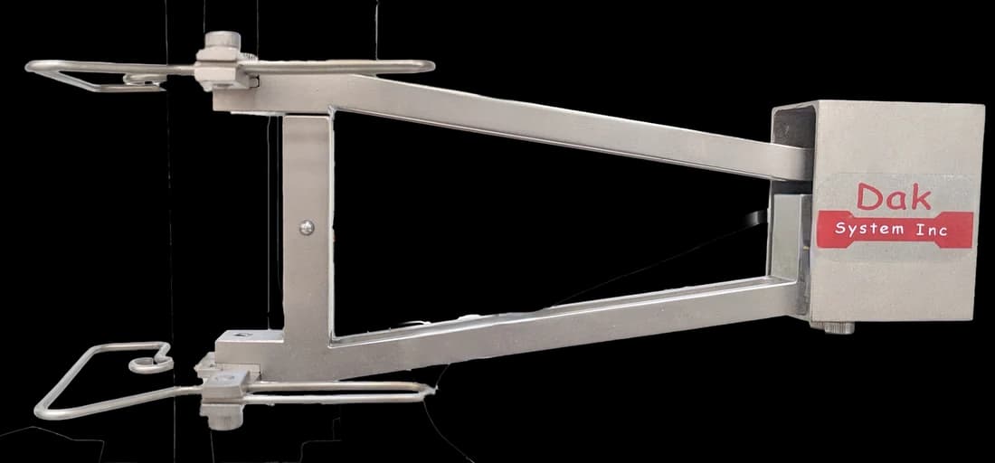
Axial and transverse clip-on devices together give the semi-automatic and automatic routes their length and width channels, at ISO 9513 class 1 in the relevant range.
Specifications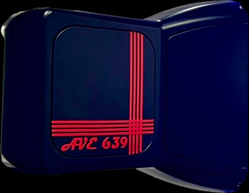
A non-contact device classified class 1 to ISO 9513 reads width along the whole gauge length rather than at one station, which is what the 2020 edition recommends where local necking starts early.
SpecificationsDak verifies against whichever standard the method names, and where a class applies our frames sit a class tighter than it asks.
| The method asks for | Dak supplies | |
|---|---|---|
| Capacity | Low — flat test pieces to ISO 6892-1 Annex B rarely draw more than a few kilonewtons; strain measurement quality and steady rate control decide the frame, not capacity. | Load cells from 1 kg to 60 ton on the Series 7200, and 0.5 to 100 kN on the Series 9000 |
| Force accuracy | ISO 7500-1 Class 1 | ISO 7500-1 Class 0.5 — a class tighter than the method asks |
| Strain measurement | An extensometer to ISO 10113: manual method none (gauge length to ±0,2 % or better, width to ±0,005 mm or better); semi-automatic ISO 9513 Class 1 or better for length with the same manual width accuracy; automatic ISO 9513 Class 1 or better on both axes with original width to ±0,1 % or better. ISO 10275: ISO 9513 Class 2 or better, tightened to Class 1 where the plastic strain ratio is determined in the same test., gauge length As ISO 6892-1:2019 Annex B for flat test pieces. ISO 10113 adds that the parallel length Lc shall be equal to or larger than (Lo + 2bo), and recommends a parallel length of at least six times the original gauge width bo where slight local necking occurs before Ag. | Certified to ISO 9513 Class 1 and ASTM E83 — non-contact video, clip-on and high-elongation |
| Gripping | wedge grips as ISO 6892-1 requires, with axial and transverse extensometry for the automatic route | Our self-tightening serrated wedge grips, with V-jaws for round specimens, built to the specimen |
| Environment | ambient 10-35 °C (23 ± 5 °C where controlled conditions are specified); no conditioning atmosphere | 3009 series chambers, −150 °C to +400 °C — temperature only |
04Run the test
The three ISO 10113 methods are not interchangeable in their instrument requirements. Where results from different methods disagree, ISO 10113 directs that the origin of the difference be investigated, and its informative Annex A sets out how.
05Calculate, report and interpret
ISO 10113 defines r from two true plastic strains and then supplies the working form; ISO 10275 defines n as the slope of a log-log line.
r = εp_b / εp_a
Valid at a single point only where the plastic strain is homogeneous. r above 1 means the test piece deformed more in width than in thickness.
r = ln(b1 / bo) / ln(Lo·bo / L1·b1)
Derived from constancy of volume, εp_a + εp_b + εp_l = 0, because length is easier and more precise to measure than thickness. It applies up to Ag and no further.
r̄ = (r0/y + r90/y + 2·r45/y) / 4
All three must come from the same method and the same strain or strain range. Other orientations may be chosen, in which case a different formula applies.
Δr = (r0/y + r90/y − 2·r45/y) / 2
The earing number. A blank drawn from sheet with a large Δr gives a cup with a wavy rim and more trim scrap.
σ = C · εpⁿ, so ln σ = ln C + n · ln εp
ISO 10275. The current edition subtracts the elastic strain from the total strain before the fit; the previous one allowed it to be ignored below 10 % of the total.
Measuring width in one place. Sheet does not neck all at once, and a width extensometer reading only the centre of the gauge length reports the reduction there as though it applied everywhere, biasing r upward. Evaluating past Ag, where constancy of volume no longer holds. A test piece showing transverse bow afterwards, which ISO 10113 makes explicit ground for declaring the test invalid. Changing the strain rate inside the evaluation range. And comparing r or n from coated sheet with bare base material, which the standard notes can differ.
06Compare methods and find answers
One measurement, three instrument routes. The choice is the producer's or the assigned laboratory's unless it has been agreed otherwise, and it changes what equipment the result depends on.
| Manual | Semi-automatic | Automatic | |
|---|---|---|---|
| Length measurement | Marked gauge, ±0,2 % or better | Extensometer, ISO 9513 class 1 or better | Extensometer, ISO 9513 class 1 or better |
| Width measurement | By hand, ±0,005 mm or better | By hand, ±0,005 mm or better | Extensometer, class 1 or better |
| Original width accuracy | ±0,005 mm or better | ±0,005 mm or better | ±0,1 % or better |
| Measured | Before and after straining | Length under load, width after | Both under load |
| Best suited to | Occasional work with no width extensometer | Routine work with an axial extensometer | Production volumes and regression over a range |
Where two methods give different answers on the same material, the difference is real and has a cause. ISO 10113 asks for it to be investigated rather than averaged away.
| ISO 10113 | ASTM E517 | ISO 10275 | ASTM E646 | |
|---|---|---|---|---|
| Reports | r | r | n | n |
| Units basis | SI | Inch-pound standard | SI | Inch-pound standard |
| Strain rate | Not above 0,008 s⁻¹, ±20 % | Test must run past yield-point elongation | Not above 0,008 s⁻¹ | Held steady and reported; n is rate-sensitive |
| Anisotropy averages | Defined in the document | Averaging is normal practice | Not applicable | Not applicable |
| Underlying tension test | ISO 6892-1 | ASTM E8/E8M practice | ISO 6892-1 | ASTM E8/E8M practice |
The ISO and ASTM values answer the same question and are not the same number by definition. A certificate that names only the property and not the method is not enough to settle a dispute.
ISO 10113 is the international method for the plastic strain ratio r of metallic sheet and strip, and ISO 10275 the method for the tensile strain hardening exponent n. Both are third editions dated 2020 from ISO/TC 164/SC 2, and both are current. They are usually run together because sheet formability needs both numbers.
r describes resistance to thinning and predicts deep drawing: a high r means the metal draws material in from the flange instead of taking it out of the thickness. n describes how quickly the metal hardens as it deforms and predicts stretch forming: a high n spreads strain along the part rather than letting it collect where it will split.
As the ratio of the true plastic width strain to the true plastic thickness strain. Because thickness is hard to measure precisely on sheet, the standard supplies a working form using only length and width, derived from constancy of volume. That form applies up to Ag, the plastic extension at maximum force, and no further.
Manual, semi-automatic and automatic. The manual method uses no extensometer and relies on marked gauge lengths measured to ±0,2 % and widths to ±0,005 mm. The semi-automatic method adds a class 1 length extensometer. The automatic method uses class 1 extensometers on both axes. Unless otherwise agreed, the choice rests with the producer or its assigned laboratory.
In the range of evaluation, the strain rate of the parallel length must not exceed 0,008 s⁻¹. ISO 10113 adds that it must be constant to within ±20 % and that any rate change should be finished at least 0,2 % strain before the evaluation range begins.
The weighted average, (r0 + r90 + 2r45)/4, is the drawability figure — how deep a cup the sheet will take before the wall fails. The degree of planar anisotropy, (r0 + r90 − 2r45)/2, is the earing figure: it predicts how wavy the rim of that cup will be and therefore how much of the blank ends up as trim scrap.
Because the width and thickness are no longer what the calculation assumes. ISO 10113 states that if the test piece shows transverse bow after the test, the test shall be considered invalid and a new one carried out, since the results could be influenced. It is a visual check, and it has to actually be made.
Yes, and ISO 10275 provides for it directly: where the plastic strain ratio is being determined at the same time, the conditions of ISO 10113 apply and the extensometer requirement tightens from class 2 to class 1. That is the efficient way to run formability work, provided the width channel is there.
A tension frame complying with ISO 6892-1, with the force-measuring system verified to ISO 7500-1 class 1 or better and extensometry to ISO 9513 in the classes each method calls for. Force capacity is rarely the constraint on sheet coupons; strain measurement quality and steady rate control are.
Discuss your specimen, test requirements and reporting needs with DAK engineering.
This page describes the method as practised. The governing text is the current edition from the issuing body. Tell us what you are testing and we will answer with the machine, the fixture and a quotation.