Testing standard

ISO 34-1

Rubber, vulcanized or thermoplastic — Determination of tear strength — Part 1: Trouser, angle and crescent test pieces

Written and technically reviewed by Dak System Inc. engineeringLast reviewed

ISO 34-1 measures the tear strength of vulcanised and thermoplastic rubber. A die-cut piece with a slit or razor nick is pulled so an existing tear is driven along it, and the force to propagate that tear divided by the piece thickness is the result, in kilonewtons per metre. Three geometries are covered and each gives its own number.

At a glance

Test type
Teara cut or nick is forced to grow
Published by
ISO
Edition
ISO 34-1:2022

What the test does

A die-cut strip of vulcanised or thermoplastic rubber is clamped in two tensile grips and pulled apart at constant jaw separation. The tear starts at a slit or a razor nick already cut into the piece, so the machine is not breaking the rubber but driving an existing tear along it. Force is recorded continuously against time, and the trace is jagged rather than smooth.

What it measures, and why it matters

The result is tear strength: the force to propagate the tear divided by the test piece thickness, reported in kilonewtons per metre. It is the property that decides whether a seal survives demoulding, whether a hose sleeve resists a nick growing into a split, and how much a tyre or conveyor cover tolerates cuts in service. Compounders use it to judge filler loading and cure state, so it works as a batch-release check and as a formulation input rather than as a service-life prediction.

The three geometries

Trouser
Slit along its length, legs clamped separatelyGives a propagation force from a running tear rather than a peak.
Angle
Torn from the apex, with or without a nick
Crescent
Nicked on the concave edge
Preferred sheet thickness
2.0 mm
The nick
Cut with a guided razor cutterIts depth sets where the tear begins, so it is guided rather than judged by eye.
Thickness
Measured on the test piece itselfIt is the divisor in the result.
Conditioning
At least 3 h, 23 ± 2 °C or 27 ± 2 °CTo ISO 23529.
Discard
Any piece tearing away from the intended path

The trace is jagged, not smooth, and that is the signal rather than noise — a tear advances in steps as it crosses filler and crosslink structure. Averaging it aggressively in software throws away what the method is measuring.

Test speed

Constant jaw separation
Set by the geometryThe trouser piece is normally run slower, so the propagation plateau is resolvable rather than passed through.
Data capture rate
High enough for a jagged traceDakHeavy smoothing rounds off the peaks a tear produces, and the error is always downward.

Calculations

Tear strengthTs

Ts = F / d

F
force to propagate the tear, N
d
thickness of the test piece, mm

Reported in kilonewtons per metre. Force per unit THICKNESS, because a tear travels along a path rather than failing across a section — there is no area to divide by.

How the test runs

  1. 01Select the geometry the material specification names.
  2. 02Die-cut pieces from sheet of the preferred 2.0 mm thickness.
  3. 03Cut the slit or nick with a guided razor cutter to the controlled depth.
  4. 04Measure thickness on the piece itself, at the tear path.
  5. 05Condition for at least three hours at the standard temperature.
  6. 06Clamp both ends squarely — for a trouser piece, one leg in each grip.
  7. 07Run at the constant jaw separation for that geometry.
  8. 08Record force continuously; expect a jagged trace.
  9. 09Take the propagation force as the method defines it for that piece.
  10. 10Discard any piece whose tear left the intended path.
  11. 11Divide by thickness and report in kN/m with the geometry named.

The fixture this method needs

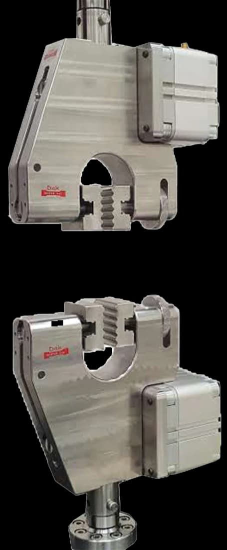
Pneumatic vice action grips with 25 mm square jaw faces
Standard 25 mm

Pneumatic Vice Action Grip

Flat vice-action faces hold a die-cut piece — or the two legs of a trouser piece — squarely and at low force, which is what a tear test needs rather than the self-tightening action a tensile dumb-bell wants.

Specifications

What the report has to contain

  • Reference to ISO 34-1 and THE GEOMETRY used
  • Compound identification and cure conditions
  • Sheet thickness and the thickness measured on each piece
  • Nick depth where applicable
  • Conditioning time and temperature
  • Rate of jaw separation
  • Tear strength in kN/m
  • How the propagation force was taken from the trace
  • Number of pieces and the statistic reported
  • Any piece discarded because the tear wandered

What the machine must be capable of

This is a low-force test. With the preferred 2.0 mm sheet, ordinary rubbers tear at roughly 10 N to 250 N and only the toughest reinforced grades approach 500 N, so a frame is chosen for fine resolution at the low end rather than for capacity. The force system must meet ISO 5893 Class 1, and it must be low in inertia: tear peaks arrive fast, and a heavy load train lags them and reads low.

Speed is fixed by geometry — 100 ± 10 mm/min jaw separation for the trouser piece, 500 ± 50 mm/min for the angle and crescent pieces. No strain or elongation measurement is required and no extensometer is needed. The demand is travel instead: the trouser tear must be followed along the whole remaining ligament while soft rubbers add substantial leg extension, and ISO 5893 warns that highly extensible materials can need over a metre of traverse.

Grips must tighten as tension rises and press uniformly across the widened end, with positioning that puts each piece symmetrically on the machine axis; wedge or pneumatic self-closing types are named for flexible materials. No dedicated tear fixture is called for — the geometry lives in the cutting die and the nick cutter. Ambient testing suffices unless another ISO 23529 temperature is chosen, which then needs a chamber.

What goes wrong in practice

Knotty tear is the common one: the tear advances in stick-slip jumps and the trace turns saw-toothed, so a median force to ISO 6133 must be read rather than a single peak. Leg extension in soft compounds eats crosshead travel and can end the test before the ligament is consumed. An inconsistent nick depth moves the tear initiation point and scatters results between operators. Grip slippage lets a leg creep, flattening the trace and understating the force.

ISO 34-1 or ASTM D624

ISO 34-1ASTM D624
GeometriesTrouser, angle, crescentFive dies: A, B, C, T and CP
Preferred thickness2.0 mmNominally 2.3 mm for Die C
Result unitskN/mkN/m or N/mm
NickGuided razor cutterControlled depth, fresh blade
Comparable to the otherNoNo

The principle is shared and the numbers are not. Pieces and rates differ, and tear strength is a property of the compound and the geometry together — so a figure from one document cannot be checked against a specification written for the other.

Questions we are asked about this test

What is ISO 34-1?

It is the international standard for tear strength of vulcanised and thermoplastic rubber. A die-cut piece carrying a slit or razor nick is pulled so an existing tear propagates along it, and the force to drive that tear divided by the piece thickness gives the result in kilonewtons per metre.

What is the difference between the trouser, angle and crescent pieces?

Where the tear starts and what force is read. The trouser piece is slit along its length and its legs clamped separately, so the tear is already running and a propagation force is read from a plateau. The angle piece tears from an apex and the crescent from a nick on its concave edge, both giving a peak. Each geometry produces its own number and they do not convert.

Why is tear strength given in kN/m?

Because the specimen does not fail across a cross-section. A tear runs along a path, and the only dimension resisting it is the thickness it has to travel through — so the result is a force per unit thickness rather than a stress. That is also why the thickness is measured on the piece itself, at the tear path.

Why is the force trace jagged?

Because a tear advances in steps rather than smoothly, as it crosses filler particles and variations in crosslink density. That roughness is the measurement rather than noise, so heavy smoothing in software rounds off the peaks and under-reports the result — an error that is systematic and always in the same direction.

What is the difference between ISO 34-1 and ASTM D624?

They share the principle and differ in the detail. ISO 34-1 defines trouser, angle and crescent pieces at a preferred 2.0 mm thickness; D624 defines five dies including a moulded constrained-path type. Rates differ too. Since tear strength depends on the geometry as much as on the compound, results from one cannot be checked against a specification written for the other.

Why must the nick be cut with a guided cutter?

Because its depth decides where the tear begins and how much of the piece resists it. A nick cut by eye varies from piece to piece, and that variation appears directly in the result as scatter that looks like compound variability. The guided razor cutter is what makes the starting condition repeatable.


Running ISO 34-1 on the Series 7200 and Series 9000

Dak verifies against whichever standard the method names, and where a class applies our frames sit a class tighter than it asks.

The method asks forDak supplies
CapacityA low-force test. With the preferred 2.0 mm sheet, ordinary rubbers tear at roughly 10 N to 250 N and only the toughest reinforced or high-tear grades approach 500 N, so a frame is chosen for fine low-end force resolution, a low-inertia load cell and long crosshead travel rather than for capacity.Load cells from 1 kg to 60 ton on the Series 7200, and 0.5 to 100 kN on the Series 9000
Force accuracyISO 5893 Class 1ISO 7500-1 Class 0.5, verified to ASTM E4, DIN 51221 and BS 1610
GrippingSelf-tightening tensile grips with symmetric positioning on the machine axis, trouser legs one per grip; die-cut trouser, angle or crescent test pieces plus a guided razor nick cutterOur vice-action grips or self-tightening serrated wedge grips, with V-jaws for round specimens, built to the specimen
EnvironmentAmbient — sheets conditioned at least 3 h and tested at a standard laboratory temperature of 23 ± 2 °C or 27 ± 2 °C per ISO 23529; a chamber only where another temperature from ISO 23529 is selected3009 series chambers, −150 °C to +400 °C — temperature only

This page describes the method as practised. The governing text is the current edition from the issuing body. Tell us what you are testing and we will answer with the machine, the fixture and a quotation.

The test it standardises

Industries that test to it

Other standards explained