
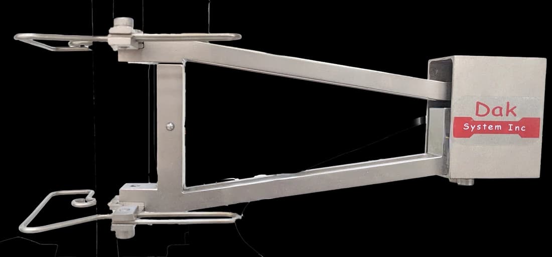
Axial & transverse
Clip-On Extensometers
A clip-on extensometer is the usual subject of this calibration; its class is established over the range of extension it will actually be used across.
Specifications
Testing standard
Metallic materials — Calibration of extensometer systems used in uniaxial testing
Written and technically reviewed by Dak System Inc. engineeringLast reviewed
ISO 9513 specifies the static calibration of extensometer systems used in uniaxial testing, covering axial and diametral systems and both contacting and non-contacting types. It assigns a class — 0,2, 0,5, 1 or 2 — where the class number is the maximum permissible relative error of gauge length in per cent.
From the test method to your testing system
Explore the DAK machines already listed for ISO 9513, then review the accuracy classes, extensometers and setup requirements below.
 Universal Testing MachineSeries 7200Explore the machine →
 Universal Testing MachineSeries 9000Explore the machine →
01Understand the method
The extensometer system is mounted in a calibration apparatus in its working configuration and known displacements are applied across the range of extension it is used over. Indicated extension is recorded against true extension at each point, the series is repeated as the standard requires, and three quantities are determined: the relative error of gauge length, the resolution, and the bias error. All three are checked against the limits for the intended class, and the system is then assigned a class — 0,2, 0,5, 1 or 2 — together with the range of extension over which that class holds. There is no test speed here, and no specimen: this calibrates the machine's strain gauge rather than testing a material, so nothing has a rate. What it fixes instead is the shape of the calibration run. Each range carries at least five increments, none spanning more than a third of the range. The number of ranges follows the span used: one where the largest displacement of interest is under ten times the smallest, two up to a hundred times, three above that. The gauge is exercised twice, then two full series are taken with it removed and refitted between them, so mounting variation is measured rather than averaged away. The room holds to ± 2 °C between 18 °C and 28 °C, read to 0,1 °C, and the apparatus must be good to a third of the error permitted for the class sought.
Whether the strain the machine reports is the strain in the specimen. The scheme mirrors ISO 7500-1 exactly: the class number is the maximum permissible relative error in per cent, so Class 0,5 permits half a per cent. Which class is needed depends entirely on what is being measured. A modulus divides a stress interval by a deliberately small strain interval — often a window only a couple of thousandths wide — so a percentage error in that strain passes into the modulus undiminished, and tight classes are essential. Elongation at break, measured over tens or hundreds of per cent, tolerates far more.
02Set the accuracy class and calibration run
The same scheme as ISO 7500-1 for force: the class number is the permitted relative error in per cent.
Like a force class, an extensometer class holds over a stated range of extension. A system classified at small extensions has not been classified at large ones, and long-travel work is exactly where that bites.
03Set up the extensometer system for calibration
Nothing, in the sense that no force is applied — the calibration apparatus imposes displacement and the frame is not involved. What the *system* must be capable of is resolution fine enough that the class is not resolution-limited, and repeatable mounting, since a clip-on gauge that seats differently each time will fail on bias error rather than on accuracy. Long-travel and non-contacting systems are explicitly in scope and are classified over their own ranges.
A clip-on extensometer is the usual subject of this calibration; its class is established over the range of extension it will actually be used across.
Specifications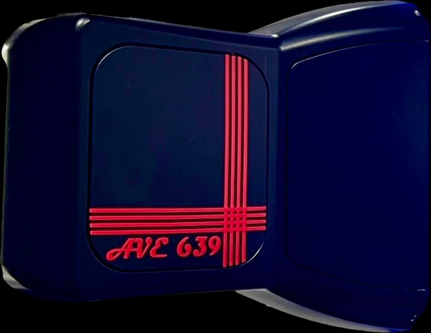
Non-contacting systems are explicitly in scope, and are calibrated as a system — optics, software and all — not as a transducer.
Specifications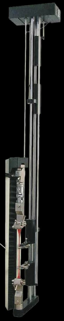
Long-travel systems are classified over their own range, and a class held at small extensions does not carry to large ones.
SpecificationsISO 9513 addresses the extensometer system used to measure extension. Calibration compares its readings with known displacements applied by a calibration apparatus. This is separate from verification of the testing machine’s force-measurement system.
The following information concerns the calibration apparatus and conditions described on this page.
The Series 7200 and Series 9000 provide the testing-machine context in which extensometers are used. The specifications below describe the testing systems; they do not establish an extensometer’s ISO 9513 class.
04Run the calibration
05Calculate, report and interpret
(indicated extension − true extension) / true extension × 100
A percentage of the extension, so the absolute tolerance shrinks as the extension falls. This is why modulus work — measured over a very small strain window — demands the tightest classes.
The class number is the maximum permissible relative error of gauge length, in per cent
Class 0,5 permits ±0,5 %. Resolution and bias error each have their own limit for the same class, and all must be met.
Et = Δσ / Δε
The modulus divides by a very small strain, so a percentage error in that strain passes straight into the modulus undiminished.
Assuming a class holds at every extension, when it holds only over the stated range — a trap in long-travel work on elastomers, films and textiles, where service extensions can far exceed anything calibrated. Changing a video system's lens or field of view and carrying the old certificate forward. Using a Class 1 system for modulus work that needed Class 0,5. And holding an immaculate force certificate alongside an uncalibrated extensometer, which still yields a wrong modulus with nothing in the result to say which half was responsible.
06Compare methods and find answers
| ISO 9513 | ASTM E83 | |
|---|---|---|
| Family | ISO | ASTM |
| Result | Class 0,2 / 0,5 / 1 / 2 | Its own classification scheme |
| Scope | Axial and diametral, contacting and non-contacting | Extensometer systems and COD gauges |
| Paired with | ISO 6892-1, ISO 527-1 | ASTM E8/E8M, ASTM D638 |
Both classify the extension-measuring chain rather than the transducer alone. The class names do not map across, so cite the standard alongside the class or the figure cannot be interpreted.
It is the ISO standard for the static calibration of extensometer systems used in uniaxial testing. It covers axial and diametral systems, and both contacting and non-contacting types, and assigns a class — 0,2, 0,5, 1 or 2. The current edition is ISO 9513:2012, the third, with a technical corrigendum issued in 2013.
That the maximum permissible relative error of gauge length is ±0,5 %. As with ISO 7500-1 for force, the class number is the tolerance in per cent, which makes the two schemes read the same way. And as with force, accuracy alone is not enough — the standard's table sets limits on resolution and bias error for each class too, and a system must satisfy all of them to hold the class.
Because of what it divides by. A modulus is a stress interval over a strain interval, and that strain interval is deliberately small — often a window a couple of thousandths wide. A percentage error in a very small strain passes straight into the modulus at full size. Elongation at break, by contrast, is measured over tens or hundreds of per cent, where the same percentage error is far less consequential.
Because what gets calibrated is the whole chain, not the transducer. For a video or laser system that means the optics, the software and the settings as configured, not a sensor in isolation. It follows that changing a lens or a field of view changes the gauge, and the calibration should be repeated — a point that is easy to overlook precisely because nothing physical has been unplugged.
No. Like a force class, an extensometer class holds over a stated range of extension, and a system classified at small extensions has not been classified at large ones. This bites hardest in long-travel work — elastomers, films, textiles — where the extensions in service can be far beyond anything the calibration covered. The range belongs on the certificate next to the class.
Yes, and it should be stated on it. The relative error is an error of gauge length, so the class is tied to the gauge length at which it was established. Using the same instrument at a different gauge length is not automatically covered, which is worth checking before assuming a certificate applies to a new test set-up.
They are separate certificates for the same machine and both are needed. ISO 7500-1 covers the force-measuring system; this covers the extension-measuring system. A modulus depends on both, so a machine with an immaculate force certificate and an uncalibrated extensometer will still produce a wrong modulus — and nothing in the result will indicate which half was at fault.
Discuss your specimen, test requirements and reporting needs with DAK engineering.
This page describes the method as practised. The governing text is the current edition from the issuing body. Tell us what you are testing and we will answer with the machine, the fixture and a quotation.