Standard Test Method for Determining Tensile Properties of Geogrids by the Single or Multi-Rib Tensile Method
Written and technically reviewed by Dak System Inc. engineering·Last reviewed
ASTM D6637 pulls geogrid specimens to failure by one of three procedures: a single rib, multiple ribs, or multiple layers of multiple ribs. Method A reports a force per rib; Methods B and C report kilonewtons per metre. The standard states its intent as quality control and conformance testing. The current edition is D6637/D6637M-15(2023).
Strips of geogrid are pulled in tension until they fail. Three procedures are defined and they differ only in how much of the grid is in the specimen: Method A tests a single rib and reports a force in newtons; Method B tests multiple ribs and reports a force per unit width in kilonewtons per metre; Method C tests multiple layers of multiple ribs and also reports kilonewtons per metre.
That choice is not a convenience. A geogrid is a structure, not a sheet, and how many ribs are gripped changes what the specimen is being asked to do.
What it measures, and why it matters
Geogrids reinforce soil. In a retaining wall, a steepened slope or a road base, the grid carries tension that the soil cannot, and the design value is a tensile strength per metre of wall width. That is the number this method produces by Methods B and C.
Single-rib testing by Method A is a different animal. It gives a force per rib, which is useful for quality control and for comparing production against a specification, but it is not directly a design value: converting it to a per-metre strength by multiplying by rib count assumes every rib takes an equal share, and in a real grid under a real grip they do not.
The standard states its own intent plainly — quality control and conformance testing of geogrids. Long-term design strengths involve creep, installation damage and durability reduction factors that no short-term tensile test provides.
Specimen, and which procedure it belongs to
A geogrid is a structure, not a sheet. How many ribs are in the specimen decides what the test is measuring.
Method A
A single geogrid rib, reported in N or lbf
Method B
Multiple geogrid ribs, reported in kN/m or lbf/ft
Method C
Multiple layers of multiple ribs, reported in kN/m or lbf/ft
Cutting
Whole ribs and junctions includedCutting through a junction changes the load path, and the specimen no longer represents the grid.
Direction
Machine and cross-machine direction, both recordedGeogrids are directional by design and a wall is reinforced in one direction.
Units
SI and inch-pound values are to be regarded separatelyThe standard states they are not exact equivalents. Choose a system and use it throughout rather than mixing.
Do not convert Method A up to a per-metre value
DakMultiplying a single-rib force by rib count assumes every rib takes an equal share. In a real grid under a real grip they do not.
Rate, and how far it has to travel
Loading
Tension to failure at the rate the method specifies
Rate
As specified in the method; the figure sits in the purchased text
Reported
Tensile strength, and strength at specified strains where required
Allow generous stroke
DakGeogrids elongate substantially before failure. A frame that runs out of travel before break has not produced a result.
Take strain from the specimen, not the crosshead
DakGrip slip and machine compliance are a large fraction of the movement on a compliant specimen. A video or long-travel extensometer following marks on the ribs is the practical instrument.
What the numbers are for
Tensile strength per unit width—
Maximum force divided by the specimen width
maximum force
peak force on the multi-rib specimen, kN
width
specimen width, m
The form used in reinforced-soil design, produced by Methods B and C.
Single-rib force—
Maximum force carried by one rib
A quality-control figure. Useful for comparing production against a specification, and not a design value on its own.
What a short-term test does not give—
Long-term design strength needs reduction factors
creep
load carried over decades, not minutes
installation damage
what backfilling does to the grid
durability
chemical and biological degradation in service
None of these come from a tensile test, and a short-term strength used directly as a design strength is a serious error.
How the test runs
01Choose the procedure the specification names — A, B or C.
02Cut specimens so whole ribs and junctions are included.
03Take specimens in both machine and cross-machine direction.
04Condition as the method requires.
05Mark the ribs for optical strain measurement if strain is to be reported.
06Clamp so load enters the ribs without crushing the junctions.
07Pull to failure at the specified rate.
08Record force, and strain from the specimen rather than the crosshead.
09Reject any specimen that slipped or failed at the grip.
10Report in the units the chosen procedure defines.
Grips and fixtures for this method
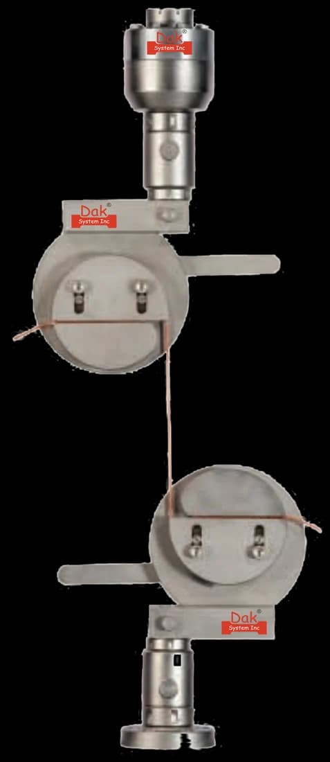
Constant pressureTJ-27
Split Capstan Grips
Where the grid is wrapped rather than clamped, a capstan introduces load progressively and avoids crushing the junctions. Wrapping distributes the grip force over a length of rib instead of concentrating it at one bite.
Strain measured optically from marks on the ribs, not from crosshead travel. On a specimen this compliant, machine compliance and grip slip are a large share of the movement, and a non-contact gauge is the only instrument that survives the elongation.
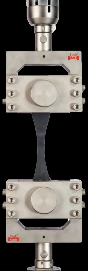
For multi-rib specimens where a clamped grip is used, wide hydraulic faces take the full specimen width at the forces a heavy uniaxial grid demands. Clamping force has to be enough to hold without crushing the junction ribs.
Strength at any specified strain, and how strain was measured
Any specimen rejected for slippage or grip failure
What the machine must be capable of
Geogrid strengths are substantial. A multi-rib specimen of a heavy uniaxial grid can demand well over 100 kN, and a frame of 100 to 300 kN with wide grips and long travel covers most commercial products. Force accuracy to ASTM E4 is the requirement.
Travel is the constraint people underestimate. Geogrids elongate significantly before failure, so the crosshead has to have the stroke to take a specimen to break without restarting.
Strain measurement, where strength at a specified strain is reported, has to come from the specimen rather than from crosshead travel: grip slip and machine compliance are large fractions of the movement on a compliant specimen. A video or long-travel extensometer following marks on the ribs is the practical answer.
What goes wrong in practice
Specimens that pull out of the grips are the dominant failure, and a partially slipped specimen produces a low strength with a plausible curve. Junctions crushed by over-tightened clamps break there rather than in the rib. Strain taken from crosshead travel overstates elongation and understates modulus. And a single-rib figure multiplied up and presented as a per-metre design strength is a reporting error that reaches drawings.
Which geosynthetic method applies to what
Four products, four methods. Substituting one for another is the commonest specification error in this area.
Geogrid
Geotextile
Geomembrane
Tensile method
ASTM D6637
ASTM D4595, ISO 10319
ASTM D6693 and D4885
Specimen
Ribs, with junctions
A wide strip of fabric
A dumbbell, or a wide strip
Reported as
N per rib, or kN/m
kN/m
Strength and elongation, or kN/m
Puncture method
Not usually applicable
ASTM D6241, ISO 12236
Grip problem
Holding a specimen that is mostly hole
Slippage on a wide fabric
Slippage on a ductile sheet
A grid is not a fabric and a fabric is not a membrane. Each method is written around how its product introduces load, and applying the wrong one produces a number that looks right and describes the grip.
Questions we are asked about this test
What is ASTM D6637?+
ASTM D6637, published as D6637/D6637M, is the test method for the tensile properties of geogrids by the single or multi-rib method. Strips of grid are pulled to failure by one of three procedures: Method A on a single rib, Method B on multiple ribs, and Method C on multiple layers of multiple ribs. The current edition is D6637/D6637M-15, reapproved in 2023.
Which procedure should be used?+
Whichever the specification names, and the choice is not cosmetic. Method A gives a force per rib in newtons and is a quality-control measure. Methods B and C give a force per unit width in kilonewtons per metre, which is the form reinforced-soil design uses. A laboratory that runs Method A because it is easier to grip has not produced the number the designer asked for.
Can a single-rib result be converted to a per-metre strength?+
Not reliably. Multiplying the single-rib force by the number of ribs per metre assumes every rib carries an equal share, and in a real grid clamped in a real grip they do not — the outer ribs and the ribs nearest the grip take more. The conversion produces a number that is usually too high, and it reaches drawings often enough to be worth stating plainly.
Is this a design test?+
No. The standard says its intent is quality control and conformance testing. A long-term design strength for a reinforced-soil structure is derived by applying reduction factors for creep, installation damage and durability to a short-term strength, and none of those factors comes from this test. Using an ultimate tensile strength directly as a design value is a serious error, not a conservative simplification.
Why are geogrids awkward to grip?+
Because the specimen is mostly hole. Load has to be introduced into the ribs without the grip crushing the junctions, and a flat clamped face on an open structure either crushes what it holds or lets the specimen pull through. Capstan or roller arrangements that wrap the grid, or clamps that engage the transverse bars rather than squeezing the ribs, are the usual answers.
What machine capacity does it need?+
More than people expect. A multi-rib specimen of a heavy uniaxial geogrid can demand well over 100 kN, so a frame of 100 to 300 kN with wide grips is realistic for commercial products. Force accuracy to ASTM E4 applies. The other constraint is stroke: geogrids elongate significantly before failure and a short-travel frame cannot take the specimen to break.
Why does the standard say SI and inch-pound values are separate?+
Because they are not exact conversions of one another. The values stated in each system are to be regarded separately as standard, so a laboratory picks one and stays in it. Mixing them — measuring in one and reporting in the other by conversion — introduces small discrepancies against the tabulated requirements, and on a conformance test those discrepancies are exactly what is being judged.

This page describes the method as practised. The governing text is the current edition from the issuing body. Tell us what you are testing and we will answer with the machine, the fixture and a quotation.