Testing standard

ASTM D6862 90 Degree Peel Resistance Testing of Adhesives

Standard Test Method for 90 Degree Peel Resistance of Adhesives

Written and technically reviewed by Dak System Inc. engineeringLast reviewed

ASTM D6862 determines the peel resistance of an adhesive bond between one rigid and one flexible adherend at approximately 90 degrees. It is useful for acceptance and quality-control testing of structural adhesives, pressure-sensitive adhesives and laminates bonded to rigid substrates.

At a glance

Test type
Peel & adhesiona bonded joint is pulled apart
Published by
ASTM
Edition
D6862-11(2021)

From the test method to your testing system

Explore the DAK machines already listed for ASTM D6862, then review the grips, measurement and setup requirements below.

Series 7200 Universal Testing MachineUniversal Testing MachineSeries 7200Explore the machine →Series 9000 Universal Testing MachineUniversal Testing MachineSeries 9000Explore the machine →
Jump to a specific section

01Understand the method

What the test does

A flexible adherend is bonded to a rigid one, cured and conditioned, and the bonded width measured. The rigid adherend is mounted on a fixture whose platform travels horizontally, the free end of the flexible member is gripped, and the two are separated at a constant crosshead speed of 254 mm/min (10 in./min) so that the peel angle stays at approximately 90 degrees throughout. The load is recorded over at least 76 mm (3 in.) of bond line with the first 25 mm (1 in.) of peel disregarded, so the higher force needed to start the peel is left out; that average is divided by the bonded width, and the way the bond gave way is recorded as percentages of each failure mode.

What it measures, and why it matters

How firmly a flexible layer holds to a rigid substrate when peeled, as an acceptance and quality-control figure. What distinguishes this method from many peel standards is that it fixes the adherend thicknesses when the specification does not — 0,60 mm for the flexible member and 1,60 mm for the rigid one. That is worth understanding rather than skimming: part of the measured peel force goes into bending the flexible adherend around the peel front rather than into breaking the bond, so a thicker flexible member raises the value with no change in the adhesive at all.

02Prepare the specimen and test settings

Defaults, where none are specified

The method fixes adherend thicknesses when the specification does not, which removes a variable that would otherwise move every result.

Configuration
One rigid adherend, one flexible
Angle
Approximately 90 degrees, held by the fixture
Default flexible adherend
0,60 mm (0,025 in) where no thickness is specifiedA default rather than a requirement — but a stated one, which is better than each laboratory choosing.
Default rigid adherend
1,60 mm (0,060 in) where none is specified
Use
Acceptance and quality controlStructural adhesives, pressure-sensitive adhesives and laminates on rigid substrates.
Record the failure mode as a percentage
DakAdhesive, cohesive, adherend failure or transfer — the force alone cannot distinguish them.

Adherend thickness changes the answer, because part of the measured force goes into bending the flexible member. Specifying defaults is how this method stops that variable floating.

Test speed

Rate
254 mm/min (10 in./min) constant crosshead speedClause 8.1. Another speed is allowed only where a test specification requires it or supplier and user agree one — and then the speed used is reported, because peel force is rate-sensitive and two figures taken at different speeds are not comparable.
Machine range required
12 mm/min (0.5 in./min) to 250 mm/min (10 in./min), constant rate of extensionClause 6.1, alongside self-aligning grips and load weighing to Practice E4. A wide speed span at low force is the awkward part of specifying a frame for this test.
Reported
Average peel force per unit width
Averaging
Over at least 76 mm (3 in.) of bond line, disregarding the first 25 mm (1 in.)Clause 8.3. That first 25 mm is the initiation peak, and it describes how the tab was made rather than how the bond holds. Readings may be taken at 12.7 mm intervals, at least six of them.
Record the adherend thicknesses actually used
DakWhether they were the defaults or not, they belong in the report — they are part of the measurement.

03Build the test setup on a DAK machine

What the machine must be capable of

Small forces, a travelling platform, and a crosshead that can be held at 254 mm/min. The method asks for a constant-rate-of-extension machine covering 12 mm/min (0.5 in./min) to 250 mm/min (10 in./min), which is a wide span for a low-force frame, and it allows another speed only where a test specification or an agreement between supplier and user names one — in which case the speed used is reported with the result. Peel forces here run from a few newtons to tens of newtons, so the load cell is chosen for the force rather than the frame — a cell sized for the machine is working below the range its accuracy class describes. The 90 degree fixture is not optional: with a fixed panel the peel front advances along the substrate while the grip stays put, so the angle opens as the test runs and the result becomes an average over a drifting geometry.

The fixture this method needs

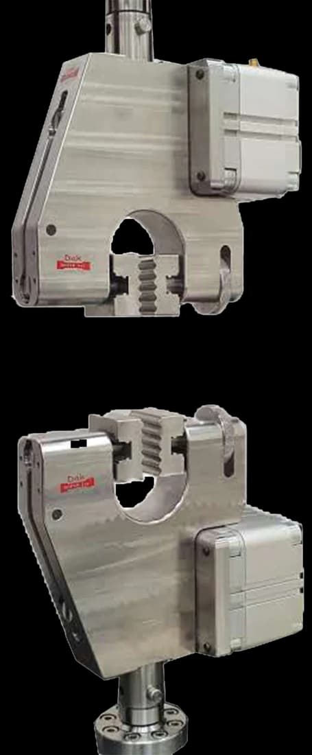
Pneumatic vice action grips with 25 mm square jaw faces
Standard 25 mm

Pneumatic Vice Action Grip

A light grip on the flexible adherend. The rigid adherend needs a travelling support so the peel angle stays at 90 degrees as the front advances — the fixture, not the frame, is what makes this test a 90 degree one.

Specifications

Running ASTM D6862 on the Series 7200 and Series 9000

Dak verifies against whichever standard the method names, and where a class applies our frames sit a class tighter than it asks.

The method asks forDak supplies
CapacityLow — 90 degree peel forces are commonly a few newtons to tens of newtonsLoad cells from 1 kg to 60 ton on the Series 7200, and 0.5 to 100 kN on the Series 9000
Force accuracyVerified at the actual peel force, not at frame capacityISO 7500-1 Class 0.5, verified to ASTM E4, DIN 51221 and BS 1610
GrippingA 90 degree peel fixture holding the rigid adherend on a travelling platformOur peel and adhesion fixtures, built to the specimen
Environment23 ± 2 °C standard laboratory atmosphere3009 series chambers, −150 °C to +400 °C — temperature only

04Run the test

How the test runs

  1. Prepare the rigid and flexible adherends to the specified surface treatment.
  2. Where no thickness is specified, use the method's defaults and record that you did.
  3. Bond, cure and condition the assemblies.
  4. Measure the bonded width.
  5. Mount the rigid adherend on the 90 degree fixture's travelling platform.
  6. Grip the free end of the flexible adherend.
  7. Select a load cell suited to a few tens of newtons.
  8. Peel at the specified constant rate, letting the platform travel so the angle holds.
  9. Peel far enough past the initiation peak to establish a steady trace.
  10. Average the force over the steady portion and divide by the bonded width.
  11. Record the failure mode as percentages and report the adherend thicknesses.

05Calculate, report and interpret

Calculations

Peel resistance

Average force over the steady peel, divided by the bonded width

Force per unit width. The initiation peak is excluded because it reports how the tab was made.

Why adherend thickness matters

Part of the force bends the flexible adherend rather than breaking the bond

A thicker flexible member takes more force to bend around the peel front, so it raises the measured value without the adhesive changing at all.

Angle dependence

A 90 degree value does not convert to a 180 degree one

What the report has to contain

  • Reference to ASTM D6862 and the edition
  • Adhesive identification and batch
  • Rigid and flexible adherend materials, thicknesses and surface treatments
  • Whether the method's default thicknesses were used
  • Bonded width and length
  • Cure schedule and conditioning
  • Rate of traverse and the averaging length
  • Average peel force per unit width
  • Failure mode as percentages
  • How the 90 degree angle was maintained

What goes wrong in practice

Peeling against a fixed panel, so 90 degrees is only true at the start. Omitting the adherend thicknesses from the report, when they are part of the measurement. Quoting a peel value without its angle, when a 90 degree and a 180 degree figure are different numbers for the same bond with no conversion between them. Averaging from the moment peel starts rather than after the first 25 mm, which reports how the tab was made. Running the test at a convenient speed instead of 254 mm/min, since peel force is rate-sensitive and the two figures are not comparable. And reporting a force with no failure mode, when adhesive, cohesive, adherend and transfer failures call for entirely different responses.

06Compare methods and find answers

ASTM D6862 or ISO 8510-2

ASTM D6862 — 90 degreesISO 8510-2 — 180 degrees
AngleApproximately 90180
AdherendsOne rigid, one flexibleOne rigid, one flexible
FixtureTravelling platformFixture holding the rigid member
ConvertibleNoNo

The same specimen type at two angles, giving two different numbers. Peel resistance depends on angle because part of the force bends the flexible adherend, and that share changes with the geometry.

Questions we are asked about this test

What is ASTM D6862?

It is the ASTM 90 degree peel test for adhesives, measuring the resistance to peel of a bond between one rigid and one flexible adherend. It is intended for acceptance and quality-control testing, and is used for structural adhesives, pressure-sensitive adhesives and laminates bonded to rigid substrates. The current designation is ASTM D6862-11(2021).

Why does the method specify default adherend thicknesses?

Because adherend thickness changes the result and would otherwise float between laboratories. Part of the measured peel force goes into bending the flexible member around the peel front rather than into breaking the bond, so a thicker flexible adherend raises the value without the adhesive being any better. Fixing 0,60 mm for the flexible member and 1,60 mm for the rigid one when nothing is specified removes that variable.

Why does the panel need to travel?

To keep the angle at 90 degrees. With a fixed panel the peel front moves along it while the grip stays put, so the angle opens progressively and the recorded value becomes an average over a changing geometry. A platform that travels horizontally as the strip comes off holds the angle where the method says it is — the fixture, rather than the frame, is what makes this a 90 degree test.

Can a 90 degree result be converted to 180 degrees?

No. Peel resistance depends on the angle because the share of the measured force that goes into bending the flexible adherend changes with the geometry. There is no general conversion, which is why ISO 8510 has separate parts for 90 and 180 degrees and why a peel value quoted without its angle cannot be checked against anything.

Why exclude the initiation peak?

Because starting a peel takes more force than continuing one, and the excess depends on how the unbonded tab was formed rather than on the adhesive. Including it reports the specimen preparation. Peeling far enough to establish a steady trace and averaging only that portion is what makes the value a property of the bond.

Why record the failure mode?

Because the modes have different consequences and the force cannot distinguish them. A cohesive failure through the adhesive says the adhesive was the limiting element. An adhesive failure at the interface says the surface preparation was. Adherend failure says the bond outlasted the material. Transfer leaves residue on the customer's part. Reporting percentages of each is what makes the number actionable.

What load cell does this need?

A small one. Peel forces here are commonly a few newtons to tens of newtons, and an accuracy class applies only down to a stated fraction of capacity — so a cell sized for the frame is working outside the range its certificate describes and produces a plausible trace with no traceable accuracy behind it.


Planning ASTM D6862 testing?

Discuss your specimen, test requirements and reporting needs with DAK engineering.

Discuss your test setup →

This page describes the method as practised. The governing text is the current edition from the issuing body. Tell us what you are testing and we will answer with the machine, the fixture and a quotation.