Testing standard

ISO 7438

Metallic materials — Bend test

Written and technically reviewed by Dak System Inc. engineeringLast reviewed

ISO 7438 is the bend test for metallic materials. A piece is bent in one continuous movement to a stated angle, to parallel legs, or to legs in contact, and the outside of the bend is then inspected. Nothing is plotted and nothing is calculated — the output is the condition of the convex surface, judged against what the product standard demands.

At a glance

Test type
Flexure & bendthe specimen is bent
Published by
ISO
Edition
ISO 7438:2020

What the test does

A piece of metal is bent, in one continuous movement, until it reaches a prescribed condition — a stated bend angle, legs parallel at a set spacing, or legs in contact. Three devices are recognised: the commonest sits the test piece across two supports and drives a former into the middle; the second replaces the supports with a V-block, so the piece folds into the vee as the former descends; the third clamps one end and wraps the free length round a former. The load is then removed and the outside of the bend inspected.

What it measures, and why it matters

Nothing is plotted and nothing is calculated. The output is the state of the convex surface after bending: either it meets what the product standard demands, or — where that standard is silent — it is judged on the absence of visible macro-cracks.

That binary answer interrogates the surface and near-surface structure, where forming operations actually fail. A plate that passes a tensile test comfortably can still split on the brake if it carries rolled-in laps, a decarburised skin or heavy segregation bands: the tensile coupon shares strain along a gauge length, while the bend concentrates it into the outer fibre. Bend results are an acceptance gate for delivery condition, forming behaviour and heat treatment, not design data.

Devices and the bend condition

Three bending devices are recognised, and the product standard chooses between them along with the former diameter and the required condition.

Two supports and a former
The commonest arrangementThe piece sits across two supports and the former is driven into the middle.
V-block and former
The piece folds into the vee
Clamp and wrap
One end clamped, the free length wrapped round a former
Bend condition
A stated angle, legs parallel, or legs in contactIn one continuous movement — not staged.
Former diameter
From the product standardIt sets the strain in the outer fibre, so it is the single most important parameter and belongs on every report.
Acceptance
From the product standardWhere the product standard is silent, the judgement is the absence of visible macro-cracks.
Mark the outer face
Before bendingDakIt is easy to inspect the compression side afterwards, and it will always look sound.

Bending

Movement
One continuous bend
Rate
Slowly, to permit free plastic flowClause 6.3. Snatching the former through the bend suppresses the plastic flow the test is there to observe.
In case of dispute
(1 ± 0,2) mm/s — 60 mm/minThe one figure the standard fixes. Set this rate whenever a result may be contested.
After bending
Release the load and inspect

How the test runs

  1. 01Take the piece in the orientation the product standard requires.
  2. 02Identify the device and the former diameter from the product standard.
  3. 03Mark the face that will be on the outside of the bend.
  4. 04Set the support spacing, or the V-block, or the clamp.
  5. 05Bend in one continuous movement to the required condition.
  6. 06Release the load.
  7. 07Inspect the convex surface without magnification unless the product standard says otherwise.
  8. 08Apply the product standard's acceptance criterion, or the absence of visible macro-cracks where it is silent.
  9. 09Record the device, the former diameter, the condition reached and the result.

Watch the test

Bending on our own frame. The film shows a plastics flexural test rather than a metals ductility bend, but the supports-and-former geometry is the arrangement this method uses most.

The fixture this method needs

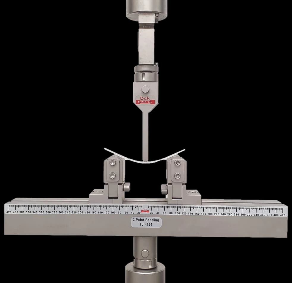
Three point bending fixture with an adjustable span and a graduated beam
Adjustable spanTJ-124

Three Point Bend Fixture

The adjustable-span beam gives the supports-and-former arrangement, with the span and former set to what the product standard calls for. No curve is recorded here — the fixture only has to deliver the geometry accurately.

Specifications

What the report has to contain

  • Reference to ISO 7438 and the product standard that sets acceptance
  • Material identification, product form and orientation
  • Piece dimensions and section
  • Which bending device was used
  • FORMER DIAMETER and support spacing
  • The bend condition reached — angle, parallel, or contact
  • Condition of the convex surface, described
  • The acceptance criterion applied, and the result

What the machine must be capable of

The standard has nothing to say about the frame. Every dimensional clause governs the jig; the press behind it is the laboratory's choice, sized to the heaviest section it must fold. Stroke deserves the closer look: bending to parallel or contacting legs eats far more travel than bending to a stated angle.

Geometry is what the standard controls. Support span is an output, not a setting — l = (D + 3a) ± a/2, from former diameter and test-piece thickness — and it must hold through the bend. Set it shorter and the supports hold the ends instead: the piece is drawn rather than folded. V-block edges are radiused in proportion to specimen thickness. Former diameter is the product standard's to set, not the laboratory's, and the nearest one to hand is a different test.

The bending force is applied slowly, so the material flows plastically rather than being snapped round the former, and clause 6.3 gives the figure that settles the argument: in case of dispute, a testing rate of (1 ± 0,2) mm/s — 60 mm/min at the former — shall be used. Set that rate whenever a result may be contested. No force accuracy class is prescribed: the method controls fixture geometry, not frame metrology, so a load reading is a process indication rather than a result. No extensometer is used.


What goes wrong in practice

Span drift is the classic. Rollers free to move, or supports set closer than the geometry allows, clamp the ends and quietly change the deformation mode; the piece looks bent and the strain history is wrong.

Former misalignment is the second: a former not centred between the supports produces an asymmetric bend, and cracks appear off the apex where nobody is looking.

Edge condition is the third and the most argued over. Rounding the edges is a requirement, not good practice, and a piece arriving at the jig square-cut or flame-cut has not met the method; what it then does at the bend is not evidence about the steel. Related: where thickness has been reduced by machining, putting the machined side in tension tests a surface the product does not have, and usually flatters it.

ISO 7438 and ASTM E290

ISO 7438ASTM E290
DevicesSupports-and-former, V-block, wrapGuided, semi-guided, free, bend-and-flatten
OutputSurface conditionSurface condition
AcceptanceFrom the product standardFrom the product specification
Calculated quantityNoneNone

Both are mechanics rather than acceptance standards. A bend result travels only with the product standard it was judged against and the former diameter it was bent around — without those two it is not a result at all.

Questions we are asked about this test

What is ISO 7438?

It is the international standard for the bend test on metallic materials. A piece is bent in one continuous movement to a stated angle, to parallel legs or to legs in contact, and the outside of the bend is inspected afterwards. The result is the condition of that surface — there is no number and no curve.

What does a bend test tell me that a tensile test does not?

It interrogates the surface and near-surface structure, which is where forming operations actually fail. A plate that passes tension comfortably can still split on the press brake if it carries rolled-in laps, a decarburised skin or heavy segregation bands — a tensile coupon shares strain along its gauge length, while a bend concentrates it into the outer fibre.

What is the pass criterion?

Whatever the product standard demands. ISO 7438 supplies only the mechanics of making the bend. Where the product standard is silent, the judgement is the absence of visible macro-cracks on the convex surface. A bend result quoted without naming the product standard it was judged against cannot be verified.

Why does the former diameter matter so much?

Because it sets the strain in the outer fibre. A tighter former means more strain and a more severe test, so the same material can pass around one former and fail around a smaller one — both correctly. The former diameter is therefore part of the result rather than a setup detail.

Which bending device should I use?

The one the product standard names. The supports-and-former arrangement is commonest; the V-block folds the piece into a vee as the former descends; the wrap device clamps one end and bends the free length round a former. They impose different constraints, so they are not interchangeable choices for an operator to make.

Is ISO 7438 design data?

No. It is an acceptance gate for delivery condition, forming behaviour and heat treatment. It answers whether the material will survive a specific imposed strain at the surface, which is a manufacturing question — not a quantity that goes into a stress calculation.

Running ISO 7438 on the Series 7200 and Series 9000

Dak verifies against whichever standard the method names, and where a class applies our frames sit a class tighter than it asks.

The method asks forDak supplies
CapacityAs with any bend test the force is set by the section and the span rather than by the method: thin sheet needs only a few kN, while thick plate and heavy bar coupons can call for several hundred kN, so bend jigs are commonly fitted to frames in the 300 kN to 600 kN class.Load cells from 1 kg to 60 ton on the Series 7200, and 0.5 to 100 kN on the Series 9000
GrippingThree-point device with two supports and a former, or a V-block and former, or a clamp-and-former deviceOur bend fixtures, built to the specimen
EnvironmentAmbient 10 °C to 35 °C in general, and 23 °C ± 5 °C where controlled conditions are called for3009 series chambers, −150 °C to +400 °C — temperature only

This page describes the method as practised. The governing text is the current edition from the issuing body. Tell us what you are testing and we will answer with the machine, the fixture and a quotation.