Testing standard

ISO 13954/13955

ISO 13954, Plastics pipes and fittings — Peel decohesion test for polyethylene (PE) electrofusion assemblies of nominal outside diameter greater than or equal to 90 mm; ISO 13955, Plastics pipes and fittings — Crushing decohesion test for polyethylene (PE) electrofusion assemblies

Written and technically reviewed by Dak System Inc. engineeringLast reviewed

ISO 13954 and ISO 13955 are the two decohesion tests for polyethylene electrofusion assemblies. ISO 13954 peels a strip from a socket assembly of 90 mm nominal outside diameter or more on a tensile machine; ISO 13955 crushes a sector of an assembly between platens and the fitting is then levered off. Neither reports a strength: both report the proportion of the fused plane that failed brittlely, judged against the value in the product standard. ISO 13954:2025 is the current second edition; ISO 13955 remains the 1997 first edition, confirmed on review in 2024.

At a glance

Test type
Peel & adhesiona bonded joint is pulled apart
Published by
ISO
Edition
ISO 13954:2025

What the test does

Both destroy a fused joint and read the fracture surface. In the peel test a strip cut from a pipe-and-socket assembly is pulled apart on a tensile machine through a shackle-type link, peeling the fused interface progressively open along the socket. In the crushing test a sector of the assembly is compressed between platens next to the socket until the pipe walls meet, after which the fitting is levered off carefully and the exposed interface examined. Both run at 23 °C plus or minus 2 °C.

What it measures, and why it matters

A fracture character rather than a strength. Loads are recorded — the peel test notes the maximum breaking load, and the crushing test notes the compressive force on a saddle piece just before the pipe walls touch — but neither figure decides anything. What decides it is read off the fracture surface. Along the fused plane each length is judged ductile, where the polyethylene has drawn and torn, or brittle, where the surfaces have simply come apart. On a socket the brittle-failure length is expressed as a percentage of the distance between the first and last coil winding; on a saddle the brittle-failure area is expressed as a percentage of the area of the fusion plane. That percentage is the result. A properly fused joint is one piece of polyethylene, so it should fail ductilely in the pipe or fitting wall, not cleanly at the coil plane. Brittle decohesion says the surfaces never fused: contaminated pipe, unscraped oxide skin, out-of-round pipe leaving a gap, or a fusion cycle that did not deliver its energy. The pass line is not in either method — both fail the assembly if the percentage exceeds the value in the relevant product standard, and ISO 13954:2025 adds an informative annex recommending a criterion.

Test pieces and how they are cut

Both methods test a joint somebody made, not a moulded coupon, so the preparation of the assembly is part of the test and is specified by a third standard.

Assembly
Prepared in accordance with ISO 11413Both methods reference it normatively. The fusion conditions used are reported with the result.
Crushing test scope
Pipes of nominal outside diameter between 16 mm and 225 mm, with socket or saddle fittings
Peel test scope
Socket assemblies of nominal outside diameter greater than or equal to 90 mmThe lower bound is in the title of ISO 13954 itself.
Sectors, crushing test
16 mm to under 90 mm: two sectors of 180°. 90 mm to 225 mm: four sectors of 90°A minimum length of pipe is left each side of the fitting — twice the nominal diameter, or 100 mm on the smaller sizes.
Saddle assemblies
Cut on a plane through the axis of the pipeThat plane is perpendicular to the one containing the pipe axis and the centreline of the tapping tee or saddle.
Peel test pieces
Strips cut from the assembly, drilled to take the bolt of the shackle-type link
Time after fusion
At least 12 h before the procedure is carried outAt least 6 h at 23 °C plus or minus 2 °C between fusion and cutting, and at least 6 h more at the test temperature after cutting.
Number of test pieces
As the product standard specifies; at least three recommended
Keep a reference set of joints you already know the answer to
DakThe result is a visual judgement about where ductile drawing stops and brittle decohesion starts. Nothing calibrates that judgement like a good joint and a bad joint side by side on the bench.

ISO 13954 was reissued as a second edition in November 2025 and its procedure was reorganised. No peel rate, dimension or tolerance is quoted here for that method, because the current clause could not be read and the withdrawn 1997 value must not be carried forward as though it still applied.

Rate, stops and temperature

Crushing rate
Constant platen approach of 100 mm/min plus or minus 10 %
Stops
Set so the platens cannot close nearer than twice the pipe wall thicknessThe stops define the end of the compression. Without them the interface is damaged before anyone reads it.
Peel rate
The rate specified by the current edition of ISO 13954Not quoted here. The tensile machine has to reach it and hold it with force enough to separate the components.
Temperature
23 °C plus or minus 2 °C throughout
Levering
Small movements only, and no impact on the test pieceWritten into the procedure, not advice. A blow tears ductile material and reads afterwards as brittle decohesion.
Do not run the crushing test without checking the stops first
DakIt takes seconds and it is the difference between reading the joint and reading what the platens did to it.

Calculations

Percentage brittle-failure decohesion, socketCc

Cc = (d2 / y) × 100

d2
total brittle-failure length in the fusion plane, parallel to the pipe axis
y
overall distance from the first to the last winding in the electrofusion socket

The reference length is the coil, not the fitting. Measuring against the socket length instead gives a percentage that is too low and looks respectable.

Percentage brittle-failure decohesion, saddleCc

Cc = (SF / ST) × 100

SF
total brittle-failure area in the fusion plane
ST
area of the fusion plane, from the fitting manufacturer's data

On a saddle the quantity is an area ratio rather than a length ratio, so the two forms of the test are not interchangeable arithmetic.

Whether the assembly passed

Compare Cc with the value in the relevant product standard

Neither method sets the acceptance figure. ISO 13954:2025 adds an informative Annex A recommending a criterion, but it is informative and the product standard still governs.

How the tests run

  1. 01Fuse the assembly in accordance with ISO 11413 and record the fusion conditions.
  2. 02Hold it at 23 °C plus or minus 2 °C for at least six hours, then cut it.
  3. 03For the crushing test, cut sectors to the table: two at 180° below 90 mm, four at 90° from 90 mm up.
  4. 04For a saddle, cut on the plane through the pipe axis instead.
  5. 05Leave the cut pieces at the test temperature for at least six hours more.
  6. 06Wait until at least twelve hours after fusion before testing.
  7. 07Measure and record the distance from the first to the last coil winding.
  8. 08Crushing: set the stops to twice the pipe wall thickness and compress next to the fitting at 100 mm/min until the inside walls of the pipe touch.
  9. 09Peel: mount the socket on the shackle-type link, hold the projecting pipe in the tensile grips, and pull along the axis at the specified rate until the piece separates.
  10. 10Lever the fitting away in small movements, without impact, and inspect the fracture surface.
  11. 11Record where the failure ran — pipe, fitting, between the windings, or at the interface.
  12. 12Measure the brittle-failure length or area, calculate the percentage, and compare it with the product standard.

Levering is where a sound joint is most often failed. If the fitting will not come away under small movements, the answer is patience, not a bigger lever.

Grips and fixtures for this method

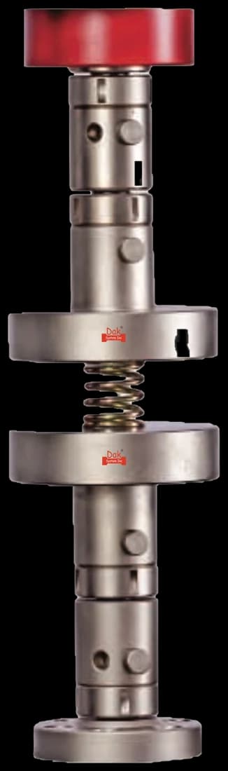
Flat-plate compression anvils, upper and lower
Rigidly fixedTJ-146

Compression Anvils

Flat, rigidly fixed platens for the crushing test. What the method adds to them is a pair of stops limiting closure to twice the pipe wall thickness, which is what ends the compression before the interface is damaged.

Specifications
Self-identifying

Load Cells

A cell matched to the job rather than to the frame. On a saddle crushing test the compressive force at the moment the pipe walls meet is a reported value, so it has to be resolved properly and not read off the bottom of a large range.

Specifications

What the report has to contain

  • Reference to ISO 13954 or ISO 13955 and the edition
  • Full identification of the sample and the material of every component
  • Nominal size of the fitting
  • Pipe dimensions before assembly — mean diameter, ovality, wall thickness and length
  • Test piece dimensions, including the free length of pipe projecting from the socket
  • The fusion conditions used to prepare the assemblies
  • Test temperature and the accuracy to which it was measured
  • Number of test pieces
  • Time between fusion and cutting, and the conditioning period
  • Test speed, on the peel test
  • Maximum breaking load on the peel test; on a saddle crushing test, the compressive force just before the pipe walls met
  • Percentage brittle-failure decohesion
  • Type of failure — interface, tearing between windings, pipe or socket
  • Any special observations, the date, and the laboratory

What the machine must be capable of

Two ordinary capabilities and one piece of discipline. The peel test needs a tensile frame able to pull at the specified slow rate with force enough to separate the components, plus the shackle-type link that lets the socket rotate as the strip peels. The crushing test needs a compression frame at a constant 100 mm/min plus or minus 10 per cent, with stops limiting platen closure to twice the pipe wall thickness — the stops define the end of the test. The discipline is the levering: the fitting is worked off in small movements with no impact, because a sharp blow tears ductile material and makes a good joint look bad.

What goes wrong in practice

Levering too hard, the commonest way to fail a joint that was sound. Testing too soon after fusion, before the joint has cooled and crystallised. Omitting the stops, so the platens crush past twice the wall thickness and damage the interface before it is read. Measuring the brittle length against the wrong reference. And reading the fracture surface without the experience to separate brittle decohesion from smooth ductile shear — the judgement is visual, and benefits most from a reference set of known joints.

Four ways of opening a fusion joint

ISO 13954 peelISO 13955 crushingISO 13956 tearISO 21751 strip-bend
JointElectrofusion socketElectrofusion socket or saddleSaddle fusion jointElectrofusion fittings and saddles
MachineTensile frame with a shackle-type linkCompression frame with limiting stopsTensile frameBend arrangement
Size90 mm nominal outside diameter and above16 mm to 225 mmAs that method setsAs that method sets
ReportsPercentage brittle-failure decohesionPercentage brittle-failure decohesionDuctility of the fusion interfaceDuctility of the fusion interface

All four ask the same question — did the two pieces of polyethylene actually become one — and they ask it of different joints with different apparatus. A product standard names the one it wants, and a result from another is not a substitute for it.

Questions we are asked about this test

What are ISO 13954 and ISO 13955?

They are the two decohesion tests for polyethylene electrofusion assemblies. ISO 13954 is the peel decohesion test, for socket assemblies of 90 mm nominal outside diameter and above, in which a strip is pulled apart on a tensile machine through a shackle-type link. ISO 13955 is the crushing decohesion test, in which a sector of the assembly is compressed between platens and the fitting is then levered off. Both are maintained by ISO/TC 138/SC 5.

Which editions are current?

ISO 13954:2025 is the second edition, published on 19 November 2025, and it withdrew both ISO 13954:1997 and that edition's Amendment 1 of 2020 on the same day. ISO 13955 is still the 1997 first edition, confirmed on systematic review in 2024, with Amendment 1:2020 alongside it. The two are commonly cited together and it is easy to assume they moved together; they did not.

What does the test actually report?

The percentage of the fused plane that failed brittlely. On a socket that is the total brittle-failure length divided by the distance from the first to the last coil winding; on a saddle it is the brittle-failure area divided by the area of the fusion plane. Loads are recorded — the peel test notes the maximum breaking load, the saddle crushing test notes the compressive force just before the pipe walls meet — but the percentage is what the assembly is judged on.

What does a brittle failure mean in practice?

That the two surfaces never fused. A properly made electrofusion joint is one continuous piece of polyethylene, so it should fail ductilely, in the wall of the pipe or the fitting, with the material drawing and tearing. A clean separation at the coil plane says something stopped the fusion: contamination on the pipe, an oxide skin that was not scraped off, out-of-round pipe leaving a gap, or a fusion cycle that did not deliver its energy.

Where does the pass or fail figure come from?

From the product standard, not from either test method. Both say the same thing: if the percentage brittle-failure decohesion is higher than the value stated in the relevant product standard, the assembly has failed. ISO 13954:2025 adds an informative Annex A recommending a criterion, but an informative annex recommends and does not require, and the product standard for the pipe system still governs.

Why is the levering singled out as a problem?

Because it is the step that most often fails a joint that was sound. The method says to use only small movements of the lever and to subject the test piece to no impacts, and that instruction is doing real work: a sharp blow tears through ductile material and leaves a surface that reads as brittle decohesion afterwards. There is no way to tell the two apart on the finished fracture face, so the discipline has to be in the doing.

What machine does the crushing test need?

A compression frame able to hold a constant platen approach of 100 mm/min plus or minus 10 %, fitted with stops that limit closure to twice the pipe wall thickness. Capacity is rarely the constraint — a pipe sector collapses well below what a general-purpose frame provides — but the stops are not optional, and on saddle pieces the compressive force just before the walls touch is a reported figure, so the load cell has to be chosen to resolve it.

Why can the joint not be tested straight after fusion?

Because it has not finished becoming a joint. The procedure is carried out at least twelve hours after fusion, with at least six hours at 23 °C plus or minus 2 °C between fusion and cutting and at least six hours more at the test temperature after the pieces are cut. A joint tested warm has not cooled and crystallised through the fusion zone, and it will not behave the way the same joint behaves in the ground.


Running ISO 13954/13955 on the Series 7200 and Series 9000

Dak verifies against whichever standard the method names, and where a class applies our frames sit a class tighter than it asks.

The method asks forDak supplies
CapacityNot prescribed. The peel test needs force enough to separate the components of the strip; the crushing test collapses a pipe sector, well within a general-purpose frame. On saddle crushing pieces the compressive force just before the pipe walls meet is itself a reported value.Load cells from 1 kg to 60 ton on the Series 7200, and 0.5 to 100 kN on the Series 9000
Force accuracyunknown — no accuracy class could be confirmed in either methodISO 7500-1 Class 0.5, verified to ASTM E4, DIN 51221 and BS 1610
GrippingPeel: shackle-type link with a tensioning chain or wire rope of at least 300 mm. Crushing: flat platens with stops limiting closure to twice the pipe wall thickness, plus a lever for separating the fitting.Our compression anvils or a fixture built for this method, built to the specimen
Environment23 °C plus or minus 2 °C throughout; at least 6 h at that temperature between fusion and cutting, at least 6 h more after cutting, and at least 12 h from fusion to test3009 series chambers, −150 °C to +400 °C — temperature only

This page describes the method as practised. The governing text is the current edition from the issuing body. Tell us what you are testing and we will answer with the machine, the fixture and a quotation.

Materials tested to it

The test it standardises

Other standards explained